


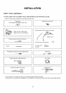
INSTALLATION
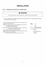
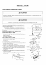
STEP 3: PREPARE THE VENTING BLOWER
[ CAUTION ]
To avoid risk of property damage, unplug the microwave oven or disconnect power at source by removing fuse
or throwing circuit breaker.
[ CAUTION ]
To avoid risk of personal injury, wear protective gloves when handling mounting plate.
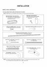
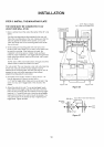
Your microwave oven is shipped with the blower assembled for roof
venting. You need to adjust the blower if you want wall-venting or room-
vented (recirculating) installation.
• DO NOT PULL OR STRETCH THE BLOWER WIRING! Pulling
and stretching the blower wiring could result in electrical shock.
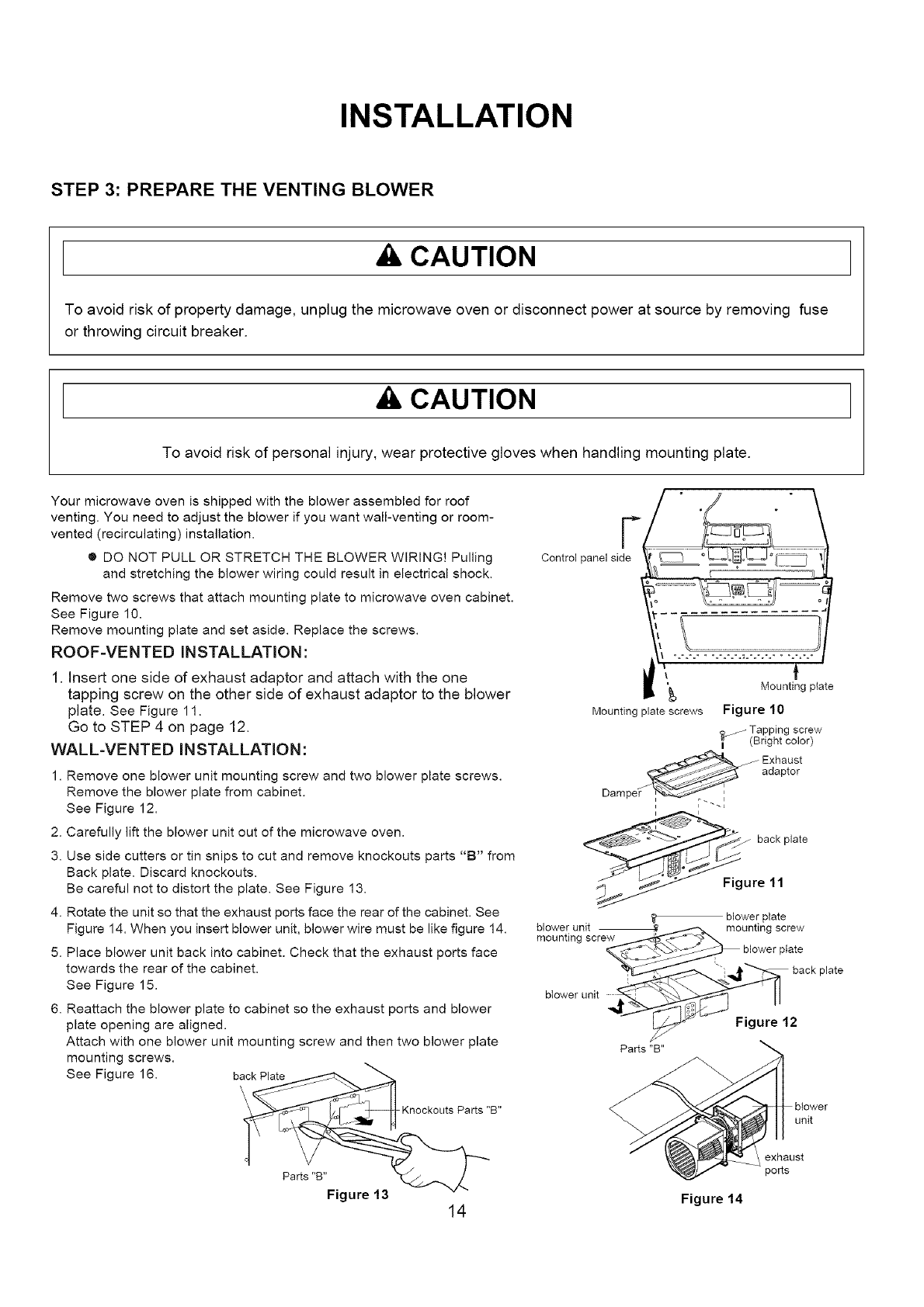
Remove two screws that attach mounting plate to microwave oven cabinet.
See Figure 10.
Remove mounting plate and set aside. Replace the screws.
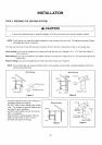
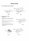
ROOF-VENTED INSTALLATION:
1. Insert one side of exhaust adaptor and attach with the one
tapping screw on the other side of exhaust adaptor to the blower
plate. See Figure 11.
Go to STEP 4 on page 12.
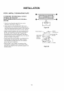
WALL-VENTED INSTALLATION:
1. Remove one blower unit mounting screw and two blower plate screws.
Remove the blower plate from cabinet.
See Figure 12.
2. Carefully lift the blower unit out of the microwave oven.
3. Use side cutters or tin snips to cut and remove knockouts parts "B" from
Back plate. Discard knockouts.
Be careful not to distort the plate. See Figure 13.
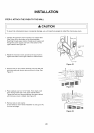
4. Rotate the unit so that the exhaust ports face the rear of the cabinet. See
Figure 14. When you insert blower unit, blower wire must be like figure 14.
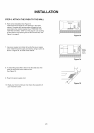
5. Place blower unit back into cabinet. Check that the exhaust ports face
towards the rear of the cabinet.
See Figure 15.
6. Reattach the blower plate to cabinet so the exhaust ports and blower
plate opening are aligned.
Attach with one blower unit mounting screw and then two blower plate
mounting screws.
See Figure 16. back Plate
-Knockouts Parts "B"
F
Control panel side
\
Mounting plate screws
Mounting plate
Figure 10
_ Tapping screw
(Bright color)
J Exhaust
adaptor
i
Dampe
back plate
Figure 11
t
blower unit
mounting scre_
blower unit ,_<_
blower plate
unting screw
blower plate
back plate
_ Figure 12
Parts "B"
unit
exhaust
po_s
Parts"B"
Figure 13 Figure 14
14