


17
SERVICE (CONT.)
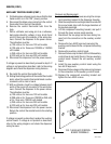
AUXILLARY CONTROL BOARD (FMD DBC-3 only)
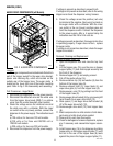
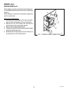
FIG. 6 AUXILIARY CONTROL BOARD
P4102.40
Location:
The auxiliary control board is located behind the lower
front access cover, mounted on the rear side of the
component bracket.
Hot Water Dispense
Test Procedure:
1. Disconnect the dispenser from the power source.
2. With a voltmeter, and using the component mount-
ing bracket as a reference (-), back probe check
for voltage at pin 1 (red wire) of J1. Connect the
dispenser to the power source. The indication must
be approximately 37 volts dc.
3. Disconnect the dispenser from the power source.
If voltage is present as described, proceed to step 5. If
voltage is not present as described, refer to the wiring
diagram and check the dispenser wiring harness.
4. Back probe check the voltage across pins 2 (black
wire) and 5 (white wire) of the six pin J2 connector
on the wiring harness with a voltmeter. Connect the
dispenser to the power source. The indication must
be:
a) 120 volts ac for two wire 120 volt models
b) 120 volts ac for three wire 120/208 or 120/240
volt models
c) 240 volts ac for two wire 240 volt models.
d) 230 volts ac for two wire 230 volt models.
5. Disconnect the dispenser from the power source.
If voltage is present as described, proceed to step 6. If
voltage is not present as described, refer to the wiring
diagram and check the dispenser wiring harness.
6. Check the voltage across the terminals of the hot
water dispense solenoid with a voltmeter. Connect
the dispenser to the power source. Press the hot
water dispense switch. The indication must be:
a) 120 volts ac for two wire 120 volt models
b) 120 volts ac for three wire 120/208 or 120/240
volt models
c) 240 volts ac for two wire 240 volt models.
d) 230 volts ac for two wire 230 volt models.
7. Disconnect the dispenser from the power source.
If voltage is present as described the hot water dispense
circuitry is operating properly. If voltage is not present
as described, replace the auxiliary control board.
Ready Light Circuit
Test Procedure:
1. Disconnect the dispenser from the power source.
2. With a voltmeter, and using the component mount-
ing bracket as a reference (-), back probe check
for voltage at pin 1 (red wire) of J1. Connect the
dispenser to the power source. The indication must
be approximately 37 volts dc.
3. Disconnect the dispenser from the power source.
If voltage is present as described, proceed to step 4. If
voltage is not present as described, refer to the wiring
diagram and check the dispenser wiring harness.
42672 122209