


21
SERVICE (cont.)
CONTROL BOARD (CONT.)
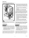
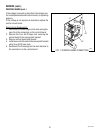
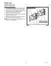
11. With a voltmeter check the voltage across the
terminals of the inlet solenoid valve. Connect the
dispenser to the power source. After a 10 second
delay, the indication must be :
a) 120 volts ac for two wire 120 volt models.
b) 120 volts ac for three wire 120/208 or 120/240
volt models.
c) 240 volts ac for two wire 240 volt models.
d) 230 volts ac for two wire 230 volt models.
12. Move the probe’s flat end to the dispenser housing.
The indication must be 0.
13. Move the probe’s flat end away from the housing.
After a 5 second delay, the indication must, again,
be:
a) 120 volts ac for two wire 120 volt models.
b) 120 volts ac for three wire 120/208 or 120/240
volt models.
c) 240 volts ac for two wire 240 volt models.
d) 230 volts ac for two wire 230 volt models.
14. Disconnect the dispenser from the power source.
If the voltage is present as described, re-install the
probe. The liquid level control circuitry is operating
properly.
If the voltage is not present as described, check the
pink probe wire and green tank wire for continuity and
check the overflow protection switch.
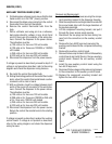
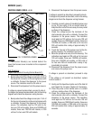
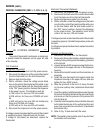
Hopper Motor Control Circuitry:
1. Disconnect the dispenser from the power source.
2. With the voltmeter, back probe check the voltage
across pins 1 & 2 of the eight pin J1 connector on
the wiring harness. Connect the dispenser to the
power source. The indication must be 24 volts ac
from the transformer.
3. Disconnect the dispenser from the power source.
If voltage is present as described, proceed to step 4.
If voltage is not present as described, refer to the wiring
diagram and check the dispenser wiring harness.
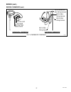
4. Check that the “Rinse/Run” switch is in the “Run”
position.
5. With a voltmeter check the voltage across the red
(+) terminal and the black (-) terminal of the auger
motor. Connect the dispenser to the power source.
Press the appropriate dispense switch. After a
delay of about .6 seconds, the indication must be
between +4.0 and +24.5 volts dc.
If the voltage is present as described, the hopper motor
control circuitry is operating properly.
If the voltage is not present as described, replace the
control circuit board.
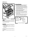
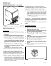
Whipper Motor and Dispense Solenoid Circuitry:
1. Disconnect the dispenser from the power source.
2. With a voltmeter, back probe check the voltage
across pins 1 & 2 of the eight pin J1 connector
on the wiring harness. Connect the dispenser to
the power source. The indication must be 24 volts
ac.
3. Disconnect the dispenser from the power source.
If voltage is present as described, proceed to step 4.
If voltage is not present as described, refer to the wiring
diagram and check the dispenser wiring harness.
4. Check that the RINSE/RUN switch is in the “Rinse”
position.
5. With a voltmeter, back probe check the voltage
across pins 2 & 4 of the six pin J2 connector on
the wiring harness. Connect the dispenser to the
power source. The indication must be:
a) 120 volts ac for two wire 120 volt models
b) 120 volts ac for three wire 120/208 or 120/240
volt models
c) 240 volts ac for two wire 240 volt models.
d) 230 volts ac for two wire 230 volt models.
6. Disconnect the dispenser from the power source.
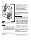
7. With a voltmeter check the voltage across the
terminals of the appropriate dispense solenoid.
Connect the dispenser to the power source. Press
the appropriate dispense switch. The indication
must be :
a) 120 volts ac for two wire 120 volt models
b) 120 volts ac for three wire 120/208 or 120/240
volt models
c) 240 volts ac for two wire 240 volt models.
d) 230 volts ac for two wire 230 volt models.
42672 122209