


26
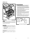
CONTROL THERMOSTAT (FMD-1,-2,-2FD,-3,-4,-5)
SERVICE (cont.)
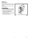
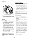
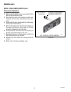
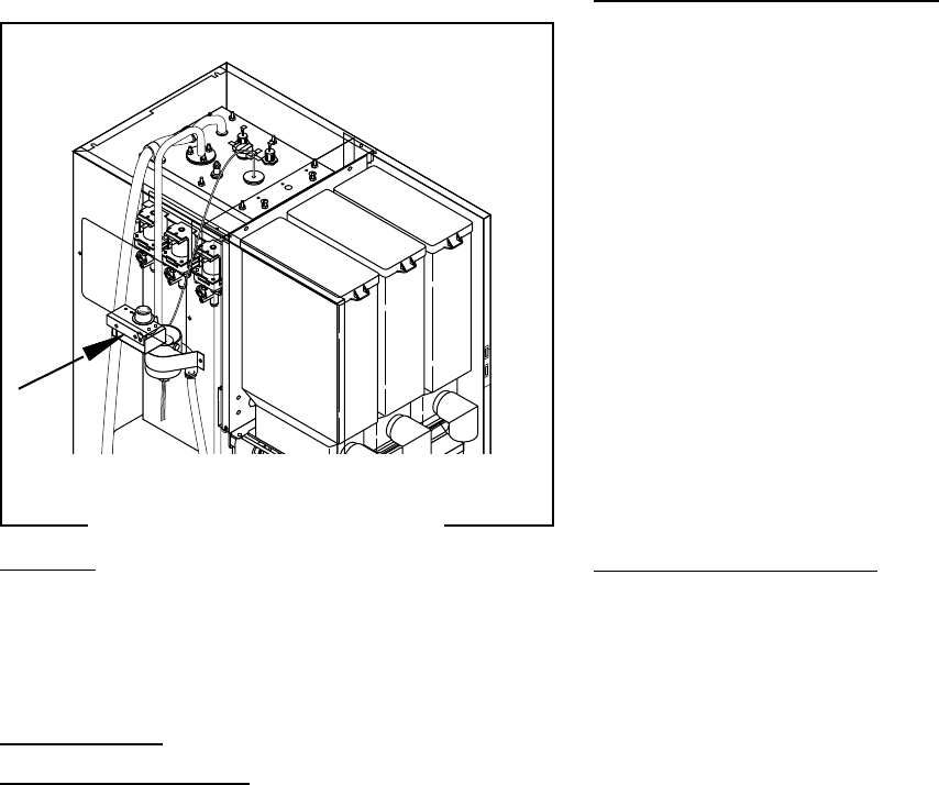
FIG. 14 CONTROL THERMOSTAT
Location:
The control thermostat (mechanical or electronic)
is located inside the dispenser on the upper left side
of the housing.
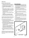
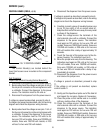
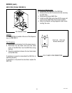
Test Procedure:
Mechanical Thermostat:
1. Disconnect the dispenser from the power source.
2. Disconnect the black wire of the control thermostat
from the black lead from the limit thermostat.
3. Remove bulb from the tank.
4. With a voltmeter, check the voltage across black
wire on the control thermostat and the white or red
wire on the tank heater with the tank heater switch
in the “ON” (lower) position. Connect the dispenser
to the power source. The indication must be:
a) 120 volts ac for two wire 120 volt models.
b) 208 volts ac for three wire 120/208 volt mod-
els.
c) 240 volts ac for two wire 240 volt models and
three wire 120/240 volt models.
d) 230 volts ac for two wire 230 volt models.
5. Disconnect the dispenser from the power source.
If voltage is present as described the control thermostat
is operating properly. Reinstall bulb into the tank.
If voltage is not present as described, replace the
thermostat.
P1445
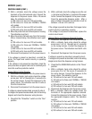
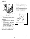
Electronic Thermostat (Optional):
1. Disconnect the dispenser from the power source.
2. Disconnect the black wire of the control thermostat
from the black wire from the limit thermostat.
3. Remove temperature probe from the tank.
4. With a voltmeter, check the voltage across the black
wire from the control thermostat and the white wire
on the tank heater with the tank heater switch in
the “ON” (lower) position. Connect the dispenser
to the power source. The indication must be120
volts ac for two wire 120 volt models.
If voltage is present as described the control thermostat
is operating properly. Reinstall temperature probe into
the tank.
If voltage is not present as described, replace the control
thermostat.
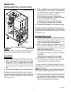
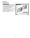
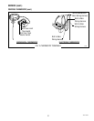
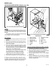
Removal and Replacement:
1. Disconnect the wires from the thermostat.
2. Remove the thermostat capillary bulb/temperature
probe by firmly pulling up on the capillary grommet
at the tank lid.
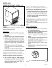
3. Loosen the two #8-32 screws securing the thermo-
stat bracket to the upper left rear of the dispenser
housing.
4. Remove thermostat bracket and thermostat as an
assembly.
5. Install the new thermostat and bracket inside the
dispenser housing on the upper left rear side and
tighten the two #8-32 screws.
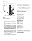
6. Slide the grommet to the line 4.5" above the bulb
on the new capillary tube (mechanical thermostat
only).
7. Insert the capillary bulb/temperature probe through
the hole in the tank lid and press the grommet firmly
and evenly so that the groove in the grommet fits
into the tank lid.
8. Carefully bend the capillary tube so that the tube and
bulb inside the tank are in the vertical position and
away from any electrical connections (mechanical
thermostat only).
9. Refer to Fig. 15 and reconnect the wires.
NOTE - The capillary tube must be clear of any electrical
termination and not kinked.
FMD-3 shown
42672 122209