


23
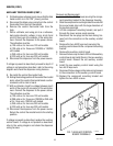
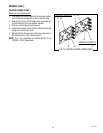
J4
J1
J2
J3
J4
J1
J2
J3
5. Disconnect the dispenser from the power source.
If voltage is present as described, proceed to step 6.
If voltage is not present as described, refer to the wiring
diagram and check the dispenser wiring harness.
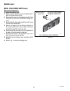
6. Carefully connect a piece of insulated jumper wire
to pin 10 (top right) of J2 on control board #1.
Keep the other end of this wire away from any metal
surfaces of the dispenser.
7. Check the voltage across the terminals of the
inlet solenoid valve with a voltmeter. Connect the
dispenser to the power source. The indication
must again be 120 volts ac for two wire 120 volt
models, three wire 120/208 volt models, three wire
120/240 volt models, or 230 volts ac for two wire
230 volt models after a delay of approximately 10
seconds.
8. Touch the free end of the jumper wire to the dis-
penser housing. The indication must be 0.
9. Move the jumper wire away from the housing. The
indication must again be 120 volts ac for two wire
120 volt models, three wire 120/208 volt models,
three wire 120/240 volt models, or 230 volts ac
for two wire 230 volt models after a delay of ap-
proximately 5 seconds.
10. Disconnect the dispenser from the power source
and remove the jumper wire.
If voltage is present as described, proceed to step
11.
If the voltage is not present as described, replace
control board #1.
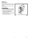
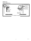
11. Gently pull the liquid level probe out of the tank lid
and inspect for corrosion. Replace it if necessary.
12. Place the probe so that neither end is in contact
with any metal surface of the dispenser.
13. Check the voltage across the terminals of the
inlet solenoid valve with a voltmeter. Connect the
dispenser to the power source. The indication
must again be 120 volts ac for two wire 120 volt
models, three wire 120/208 volt models, three wire
120/240 volt models, or 230 volts ac for two wire
230 volt models after a delay of approximately 10
seconds.
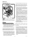
SERVICE (cont.)
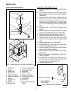
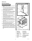
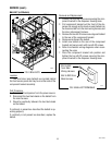
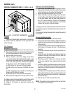
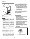
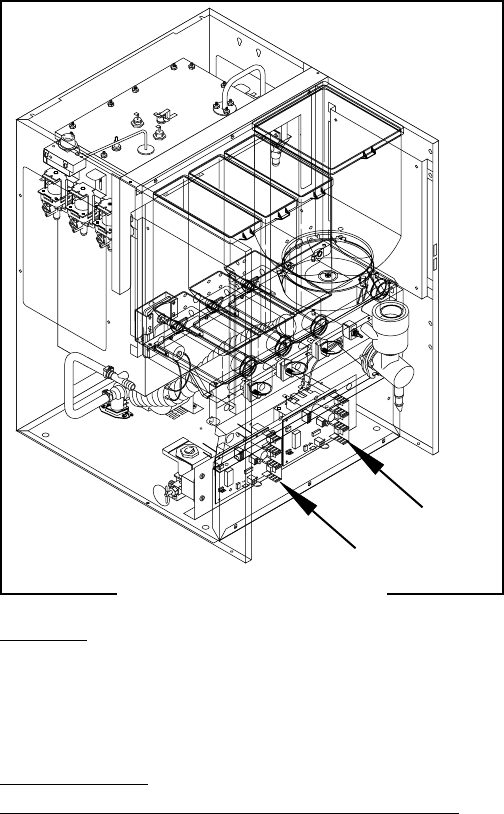
CONTROL BOARD (FMD-3,-4,-5)
FIG. 12 CONTROL BOARD
Location:
The Control Board(s) are located behind the
lower front access cover mounted on the component
bracket.
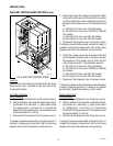
Test Procedure:
Liquid Level Control Circuitry(Control Board #1):
1. Disconnect the dispenser from the power source.
2. Back probe check the voltage across pins 5 & 6 of
the six pin J3 connector on the wiring harness with
a voltmeter. Connect the dispenser to the power
source. The indication must be 24 volts ac.
3. Disconnect the dispenser from the power source.
If voltage is present as described, proceed to step 4.
If voltage is not present as described, refer to the wiring
diagram and check the dispenser wiring harness.
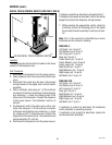
4. Back probe check the voltage across pins 1 & 4 of
the four pin J4 connector on the wiring harness with
a voltmeter. Connect the dispenser to the power
source. The indication must be 120 volts ac for
two wire 120 volt models, three wire 120/208 volt
models, three wire 120/240 volt models, or 230
volts ac for two wire 230 volt models.
P4095
#1
#2
FMD-4 shown
42672 122209