


18
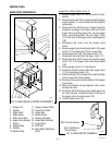
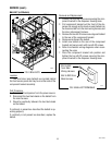
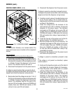
Removal and Replacement:
1. Loosen the two #8-32 screws securing the compo-
nent mounting bracket to the dispenser housing.
2. Slide the component mounting bracket forward until
the screw heads align with the large diameters of
the keyhole openings.
3. Lift the component mounting bracket, and pull it
through the lower access panel opening.
4. Disconnect the two plugs on the main wiring har-
ness from the connectors on the auxiliary control
board.
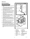
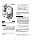
5. Remove the two #6-32 keps nuts securing the
auxiliary control board to the component mounting
bracket.
6. Remove the auxiliary control board.
7. Remove the two snap-in stand-offs from the auxiliary
control board and install them in the new auxiliary
control board. Discard the old auxiliary control
board.
8. Install the new auxiliary control board using the
two #6-32 keps nuts.
9. Reconnect the two plugs on the main wiring harness
to the connectors on the auxiliary control board.
10. Replace the component mounting bracket and
tighten the two #8-32 screws.
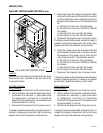
4. On the dispenser whipper panel, ensure that the tank
heater switch is in the “ON” (lower) position.
5. Disconnect the black wire coming from the control
thermostat from the limit thermostat.
6. Remove the control thermostat bulb from the
tank.
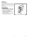
7. With a voltmeter, and using pin 5 as a reference,
back probe check for voltage, in turn, at pin 3 and
pin 6 of the six pin J2 connector of the wiring har-
ness. Connect the dispenser to the power source.
The indication must be :
a) 120 volts ac for two wire 120 volt models
b) 120 volts ac for three wire 120/208 or 120/240
volt models
c) 240 volts ac for two wire 240 volt models.
d) 230 volts ac for two wire 230 volt models.
8. Disconnect the dispenser from the power source.
If voltage is present as described, proceed to step 9. If
voltage is not present as described, refer to the wiring
diagram and check the dispenser wiring harness.
9. Re-install the control thermostat bulb.
10. Noting the starting position of the control thermostat
knob, adjust the control thermostat knob counter-
clockwise until a click is heard.
11. With a voltmeter, check for voltage between pins 3
and 6 of the six pin J2 connector of the wiring har-
ness. Connect the dispenser to the power source.
The indication must be:
a) 120 volts ac for two wire 120 volt models
b) 208 volts ac for three wire 120/208 or 240 volts
ac for three wire 120/240 volt models
c) 240 volts ac for two wire 240 volt models.
d) 230 volts ac for two wire 230 volt models.
12. Disconnect the dispenser from the power source.
Return the control thermostat knob to the starting
position.
If voltage is present as described, replace the auxiliary
control board. If voltage is not present as described,
refer to the wiring diagram and check the dispenser
wiring harness.
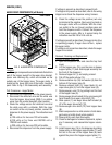
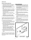
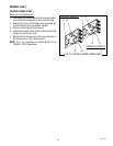
FIG. 7 AUXILIARY CONTROL
BOARD TERMINALS
P1996.80
J2
J1
SERVICE (CONT.)
AUXILLARY CONTROL BOARD (CONT.)
42672 122209