


28
P1449
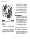
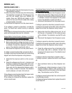
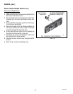
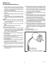
FIG. 17 DISPENSE SWITCH TERMINALS
DISPENSE SWITCHES (FMD-1,-2,-2FD,-3,-4,-5)
SERVICE (cont.)
If voltage is present as described, proceed to #7.
If voltage is not present as described, refer to the wiring
diagram and check the dispenser wiring harness.
7. Check for continuity across the terminals (top right
to top left; bottom right to bottom left) of the dis-
pense switch with the switch in the “ON” position.
Continuity must not present when the switch is in
the “OFF” released position.
If continuity is present as described, reconnect the
connector to the door interconnect wiring harness, the
switch is operating properly.
If continuity is not present as described, replace the
switch.
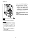
Removal and Replacement
1. Open the dispenser door.
2. Remove the six #8-32 screws securing the bottom
door cover and remove cover.
3. Disconnect the wires on the dispense switch from
the door interconnect wiring harness.
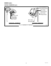
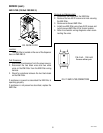
4. Compress the clips inside the door on the dispense
switch and gently push the switch through the
opening
5. Push the new switch into the opening and spread
the clips to hold the switch in the door.
6. Reconnect the wires to the dispense switch from
the door interconnect wiring harness.
7. Reinstall the door bottom cover using six #8-32
screws.
8. Refer to schematic wiring diagrams when recon-
necting the wires.
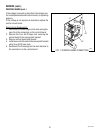
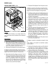
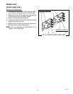
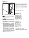
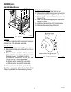
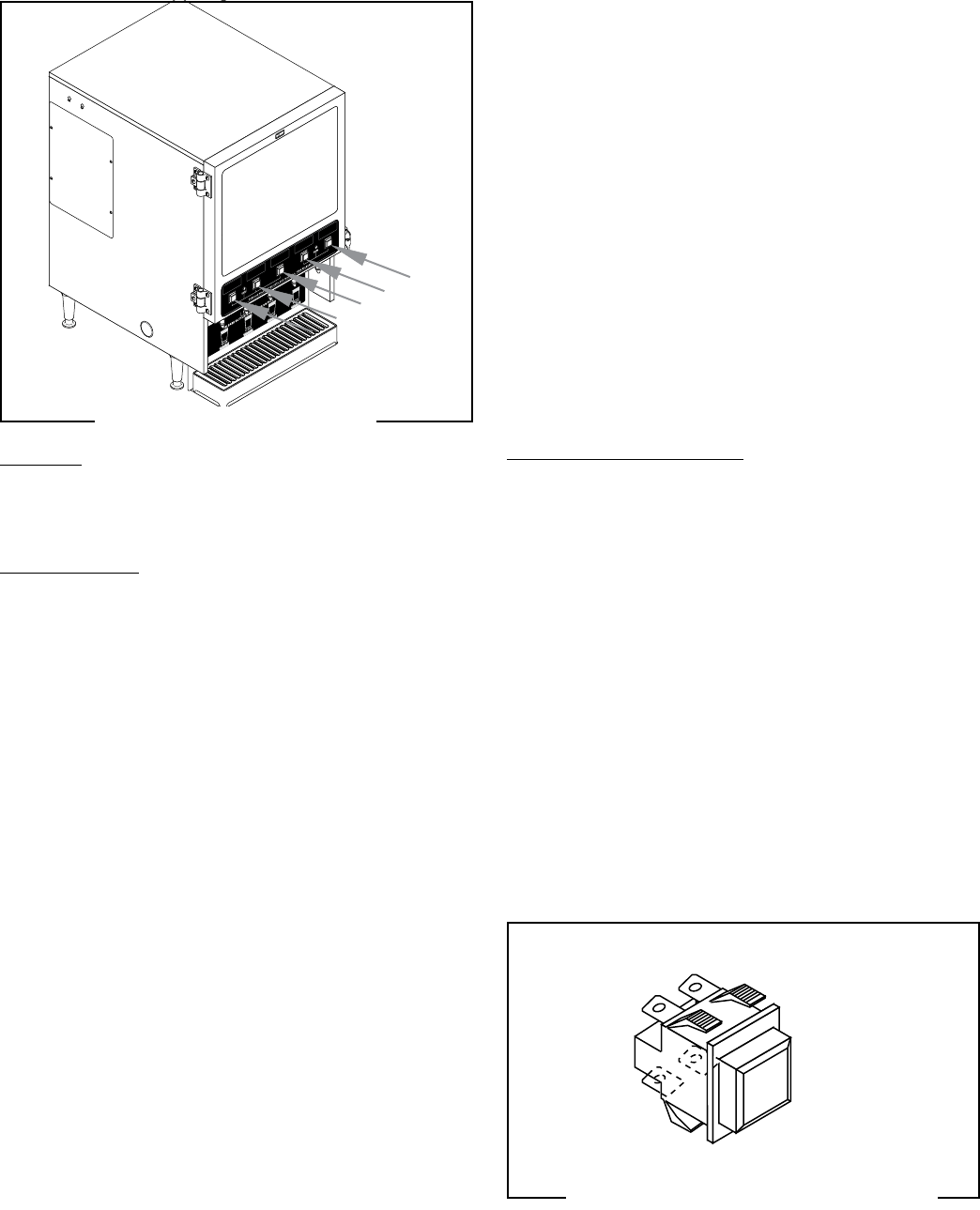
FIG.16 DISPENSE SWITCHES
P2636
Location:
The dispense switches are located on the lower
outside of the dispenser door.
Test Procedure:
1. Disconnect the dispenser from the power source.
2. Open the dispenser door and remove the bottom
door cover.
3. Disconnect the wires from the door interconnect wir-
ing harness to the dispense switch to be tested.
4. Check for voltage across the black and red/white
wires for the dispense switch to be teseted from
the door interconnect wiring harness. Connect the
dispenser to the power supply. The indication must
be:
a) 120 volts ac for two wire 120 volt models.
b) 120 volts ac for three wire 120/208 volt or 120/240
volt models.
c) 230 volts ac for two wire 230 volt models.
5. Disconnect the dispenser from the power source.
If voltage is present as described, proceed to #6.
If voltage is not present as described, refer to the wiring
diagram and check the dispenser wiring harness.
6. With a voltmeter, check the voltage across the
remaining two wires of the dispense switch being
tested from the door interconnect wiring harness.
Connect the dispenser to the power source. The
indication must be +5 volts dc.
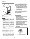
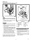
FMD-5 shown
42672 122209