


50
SERVICE (cont.)
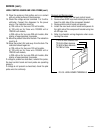
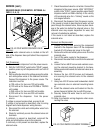
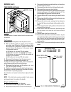
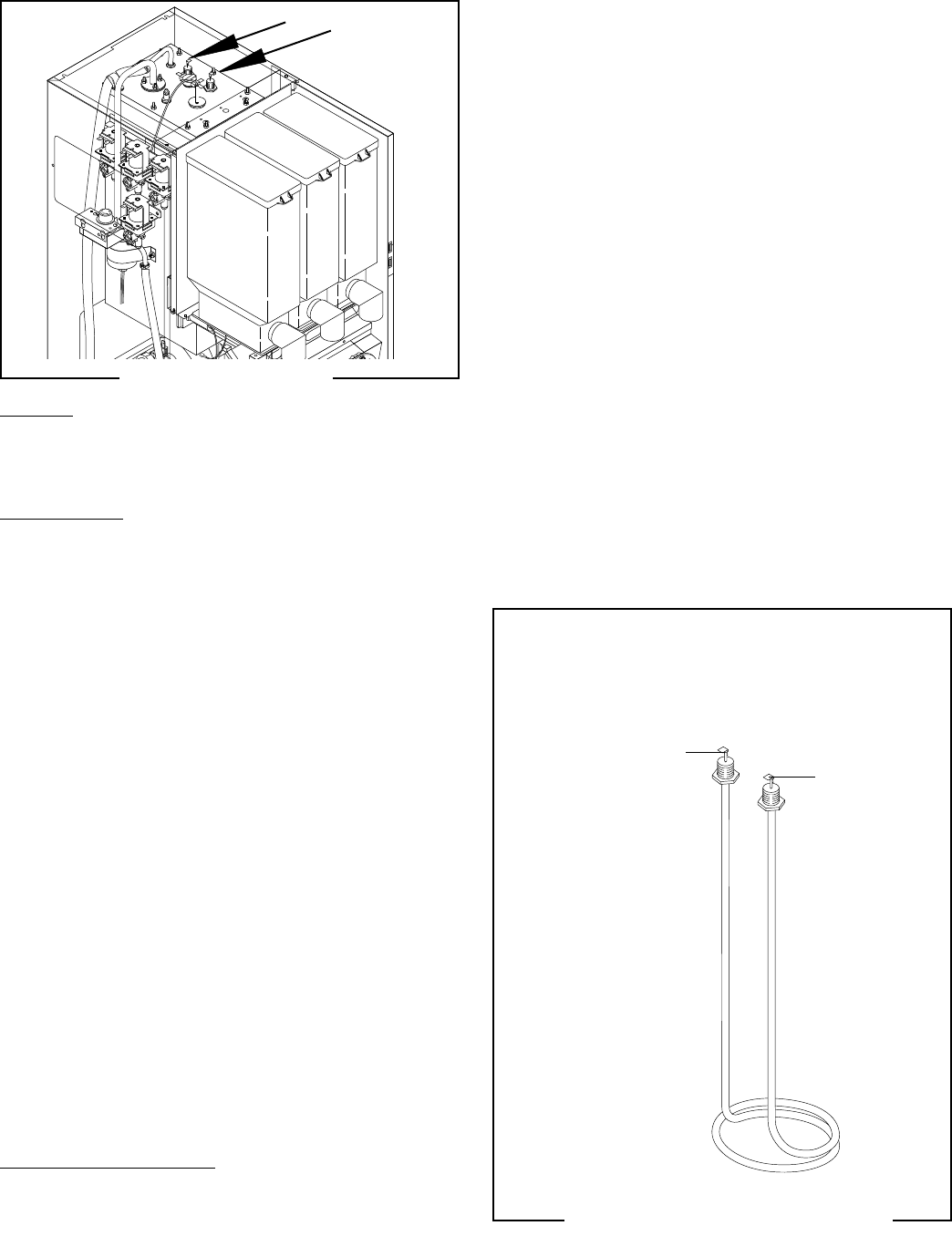
TANK HEATER (all Models)
FIG. 50 TANK HEATER
P4102.40
Location:
The tank heater is located inside the tank and secured to
the tank lid.
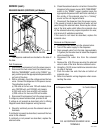
Test Procedure:
1. Disconnect the dispenser from the power source.
2. With a voltmeter check the voltage across the black
and white wires 120 volt or 240 volt models or black
and red wires for 120/208 volt models or 120/240 volt
models. Connect the dispenser to the power source.
The indication must be:
a) 120 volts ac for two wire 120 volt models;
b) 208 volts ac for three wire 120/208 volt models.
c) 240 volts ac for three wire 120/240 volt models and
two wire 240 volt models.
d) 230 volts ac for two wire 230 volt models.
3. Disconnect the dispenser from the power source.
If voltage is present as described, proceed to #4.
If voltage is not present as described, refer to the dispenser
wiring diagram and check the wiring harness.
4. Disconnect the black wire and the white or red wire
from the tank heater terminals.
5. Check for continuity across the tank heater terminals.
If continuity is present as described, reconnect the wires,
the tank heater is operating properly.
If continuity is not present as described, replace the tank
heater.
NOTE - If the tank heater remains unable to heat, remove
and inspect heater for cracks in the sheath.
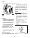
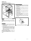
Removal and Replacement:
1. Shut off water supply to the dispenser.
2. Disconnect the water supply tube on the tank lid.
3. Disconnect the black wires on the limit thermostat.
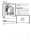
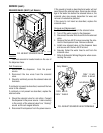
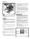
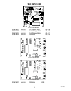
FIG. 51 TANK HEATER TERMINALS
P1218
WHI or RED to Main
Wiring Harness
BLK to Limit
Thermostat
FMD DBC-3 shown
4. Disconnect the black wire and the white or red wire from
the tank heater terminals.
5. Disconnect the pink wire from the liquid level probe.
6. Disconnect the green wire from the tank.
7. Remove the thermostat capillary bulb/temperature probe
by firmly pulling up on the capillary at the tank lid. This
will disengage the grommet from the tank lid.
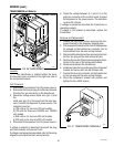
8. Remove the ten #8-32 nuts securing the tank lid to the
tank.
9. Remove tank lid with limit thermostat, liquid level probe
and tank heater as an assembly.
10. Remove the two hex nuts securing the tank heater to
the tank lid. Remove tank heater with gaskets and dis-
card.
11. Install new tank heater with gaskets on the tank lid and
secure with two hex nuts.
12. Install tank lid with limit thermostat, liquid level probe
and tank heater on the tank and secure with ten #8-32
hex nuts.
13. Connect water inlet line to the tank lid.
14. Reconnect the black wires to limit thermostat, the pink
wire to the liquid level probe and the green wire to the
tank. Refer to the limit thermostat and the liquid level
board and probe sections in this manual when recon-
necting wires.
15. Refer to Fig. 51 when reconnecting the wires to the tank
heater.
Resistance Values
120V 7.8 - 9.2 ohms @ 68° - 75°F
240V 15.3 - 17.9 ohms @ 68° - 75°F
42672 122209