


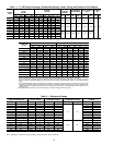
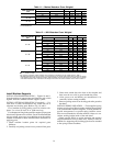
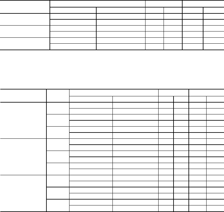
Table 11 — Marine Waterbox Cover Weights*
HEAT EXCHANGER
SIZE
DESIGN MAXIMUM WATER PRESSURE COOLER CONDENSER
psi kPa lb kg lb kg
31-33
150 1034 1667 756 1092 495
300 2068 2280 1034 1436 651
41-48
150 1034 2236 1015 1275 579
300 2068 3060 1389 1660 754
51-57
150 1034 — — 1643 746
300 2068 — — 2243 1018
*Heat exchangers with marine waterboxes have heavier dry and operating weights than heat exchangers with nozzle-
in-head waterboxes.
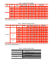
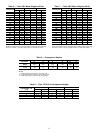
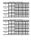
Table 12 — NIH Waterbox Cover Weights*
HEAT EXCHANGER
SIZE
PASSES
DESIGN MAXIMUM WATER PRESSURE COOLER CONDENSER
psi kPa lb kg lb kg
31-33
1
150 1034 1880 853 — —
300 2068 2748 1247 — —
2
150 1034 2168 983 1356 615
300 2068 3107 1409 1959 889
3
150 1034 2105 955 1283 582
300 2068 2991 1357 1828 829
41-48
1
150 1034 2997 1361 1735 788
300 2068 4225 1918 2510 1140
2†
150 1034 2984 1355 1885 856
300 2068 4188 1901 2590 1176
3
150 1034 3035 1378 1777 807
300 2068 4244 1927 2539 1153
51-57
1
150 1034 — — 2032 923
300 2068 — — 2940 1335
2†
150 1034 — — 2649 1203
300 2068 — — 3640 1653
3
150 1034 — — — —
300 2068 — — — —
NIH — Nozzle-in-Head
*The 150 psig (1034 kPa) 2-pass waterbox cover weights are included in the dry weight shown in Table 1.
†Two different waterbox covers arepresent on2-pass machines.The weight shownin this table represents the weight
of the waterbox cover that contains the nozzles. Ablank waterbox cover is also present on 2-pass units. The weight
of the blank waterbox cover is identical to the weight of the same size marine waterbox cover. Refer to Table 11.
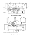
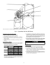
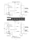
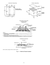
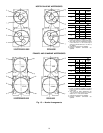
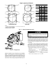
Install Machine Supports
INSTALL STANDARD ISOLATION — Figures 10 and 11
show the position of support plates and shear flex pads, which
together form the standard machine support system.
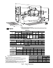
INSTALL OPTIONAL ISOLATION (if required) — Un-
even floors or other considerations may dictate the use of
soleplates and leveling pads. Refer to Fig. 10 and 11.
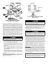
Level machine by using jacking screws in isolation sole-
plates. Use a level at least 24 in. (600 mm) long.
For adequate and long lasting machine support, proper grout
selection and placement is essential. Carrier recommends that
only pre-mixed, epoxy-type, non-shrinking grout be used for
machine installation. Follow manufacturer’s instructions in
applying grout.
1. Check machine location prints for required grout
thickness.
2. Carefully wax jacking screws for easy removal from grout.
3. Grout must extend above the base of the soleplate and
there must be no voids in grout beneath the plates.
4. Allow grout to set and harden, per manufacturer’s in-
structions, before starting machine.
5. Remove jacking screws from leveling pads after grout has
hardened.
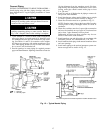
INSTALL SPRING ISOLATION — Field-supplied spring
isolators may be placed directly under machine support plates
or be located under machine soleplates. Consult job data for
specific arrangement. Low profile spring isolation assem-
blies are recommended so that the machine is kept at a con-
venient working height inside of the tube sheet.
Obtain specific details on spring mounting and machine
weight distribution from job data. Also, check job data for
methods for supporting and isolating pipes that are attached
to the spring-isolated machines.
14