


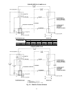
To Separate Cooler From Utility Vessel
1. Remove condenser (see previous section).
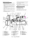
2. Cut copper lines (Fig. 6, Items 6 and 8).
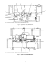
3. Unbolt liquid refrigerant line at flange (Fig. 7, Item 3).
4. Connect rigging to all four corners of the cooler before
lifting the unit.
5. Unbolt connections to the utility vessel (Fig. 6, Items 5
and 10).
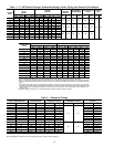
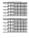
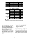
To Assemble the Machine
1. Follow disassembly instructions (in reverse order) and bolt
all flanges back together using a gasket sealant. The fol-
lowing torque requirements are specified:
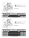
FIG. ITEM NO.
TORQUE
ft-lb N-m
6
3 580 786
1 or 4 170 230
5 and 10 840* 1139*
7
1 380 515
4 and 5 250 340
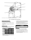
8
1 and 6 280 380
2 170 230
3 380 515
57196
N-m — Newton Meters
*This torque is used to rig the entire machine. Once the machine
is in place, if no further rigging is anticipated, the bolt torque can
be reduced to 280 ft-lb (380 N-m).
2. All gasketed or O-ring joints which have been disas-
sembled must be assembled using new gaskets and O-rings.
These new gaskets and O-rings (along with gasket seal-
ant, O-ring lubricant, and copper line couplings) are avail-
able through your Carrier representative.
3. Braze all copper lines back together using a suitable braz-
ing material for copper. Carrier recommends an AWS
(American Welding Society) Classification BCuP-2.
Do not tilt the compressor; oil is contained in the oil
sump.
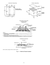
Additional Notes
1. Use silicon grease on new O-rings when refitting.
2. Use gasket sealant on new gaskets when refitting.
3. Cooler, utility, and condenser vessels may be rigged ver-
tically, as separate components. Rigging should be fixed
to all four corners of the tube sheet.
4. New gaskets, grease for O-rings, and gasket sealant for a
complete take-apart operation are available in a kit. Con-
tact your Carrier representative.
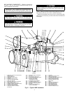
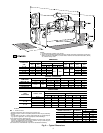
NOTE: Item numbers are referenced in Rigging the Machine, Component Disassembly section.
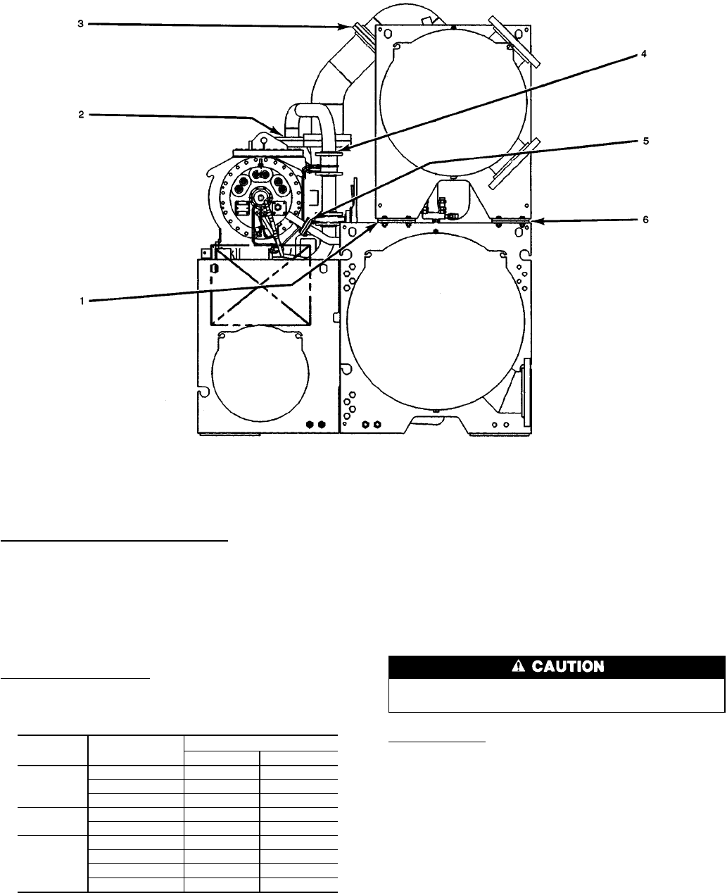
Fig.8—Typical Motor End View (19EX Shown)
8