


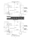
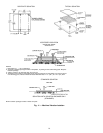
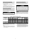
INSTALL VENT PIPING TO RELIEF DEVICES — The
17/19EX chiller is factory equipped with relief devices on
the cooler and utility vessels. Refer to Fig. 2 and 3, and
Table 13 for size and location of relief devices, as well as
information that will help determine pipe size. Vent relief
devices to the outdoors in accordance with ASHRAE 15
(latest edition) Safety Code for Mechanical Refrigeration and
all other applicable codes. To ensure relief valve serviceabil-
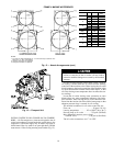
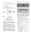
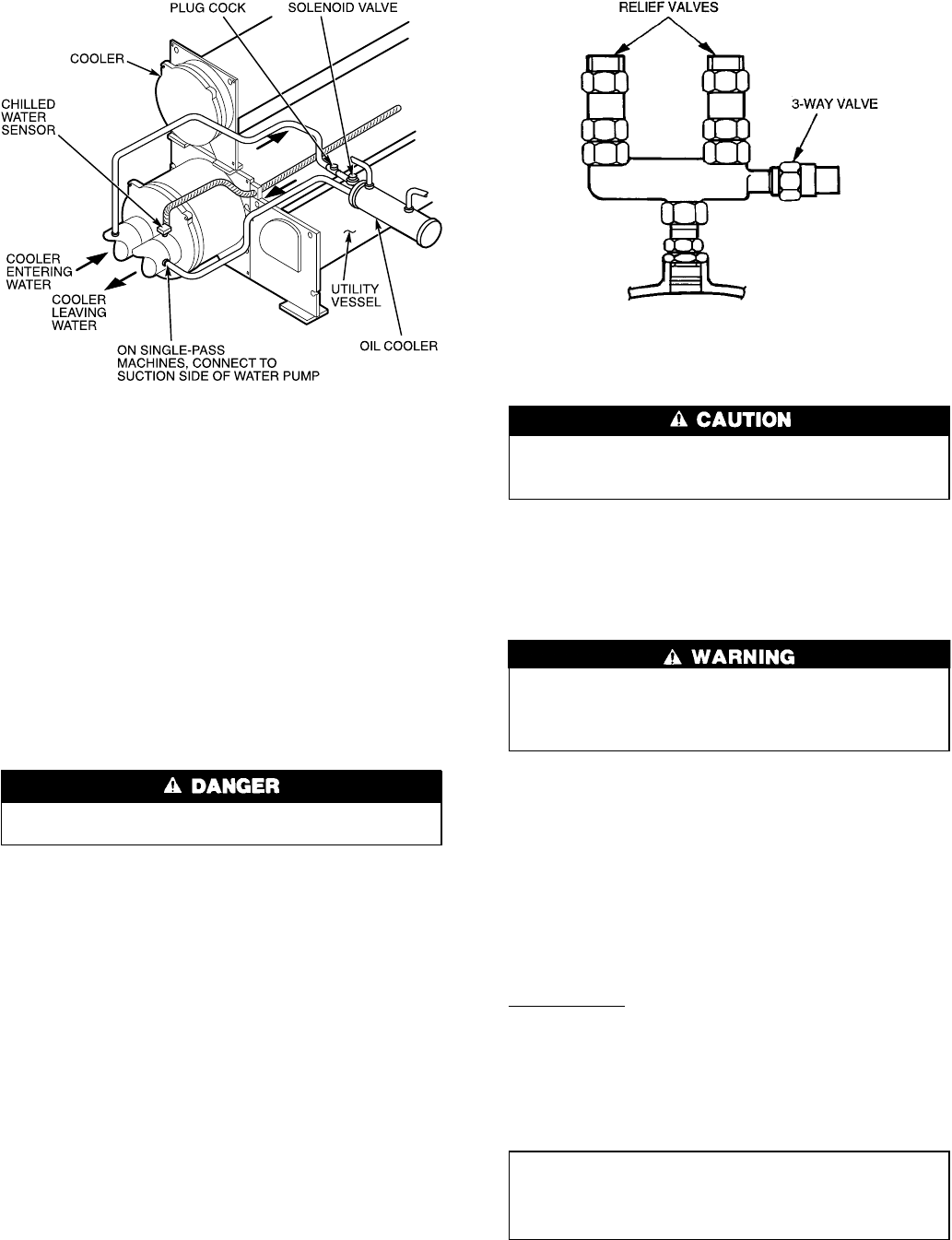
ity, and as required in ASHRAE 15, latest edition, 3-way
dual shutoff valves and redundant relief valves are installed
on the economizer/storage vessel, refer to Fig. 16.
NOTE: The 3-way dual shutoff valve should be either front
seated or back seated. Running the refrigeration system with
the valve stem in the center position can reduce total relief
capacity and cause valve chattering.
Refrigerant discharged into confined spaces can dis-
place oxygen and cause asphyxiation.
1. If relief device piping is manifolded, the cross-sectional
area of the relief pipe must at least equal the sum of the
areas required for individual relief pipes.
2. Provide a pipe plug near outlet side of each relief device
for leak testing. Provide pipe fittings that allow vent pip-
ing to be disconnected periodically for inspection of valve
mechanism.
3. Piping to relief devices must not apply stress to the
device. Adequately support piping. A length of flexible
tubing or piping near the device is essential on spring-
isolated machines.
4. Cover the outdoor vent with a rain cap and place a con-
densation drain at the low point in the vent piping to pre-
vent water build-up on the atmospheric side of the relief
device.
Make Electrical Connections — Field wiring must
be installed in accordance with job wiring diagrams and all
applicable electrical codes.
Do not run 120-v wiring into the control center. The
control center should only be used for additional extra
low-voltage wiring (50 v maximum).
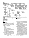
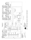
Wiring diagrams in this publication (Fig. 17-23) are for
reference only and are not intended for use during actual in-
stallation; follow job specific wiring diagrams.
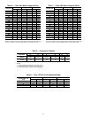
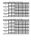
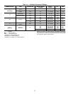
Specific electrical ratings for individual components are
shown in Table 14.
Do not attempt to start compressor or oil pump — even
for a rotation check — or apply test voltage of any kind
while machine is under dehydration vacuum. Motor in-
sulation breakdown and serious damage may result.
CONNECT CONTROL INPUTS — Connect the control in-
put wiring from the chilled and condenser water flow switches
to the starter terminal strip. Wiring may also be specified for
a spare safety switch, and a remote start/stop contact can be
wired to the starter terminal strip, as shown in Fig. 17 and
18. Additional spare sensors and Carrier Comfort Network
modules may be specified as well. These are wired to the
machine control center as indicated in Fig. 22 and 23.
CONNECT CONTROL OUTPUTS — Connect auxiliary
equipment, chilled and condenser water pumps, and spare
alarms as required and indicated on job wiring drawings.
Connect Starter — Assemble and install compressor termi-
nal box in desired orientation, and cut necessary conduit open-
ings in conduit support plates. Attach power leads to com-
pressor terminals in accordance with job wiring drawings,
observing caution label in terminal box. Use only copper con-
ductors. The motor must be grounded in accordance with
NEC (National Electrical Code), applicable local codes, and
job wiring diagrams.
IMPORTANT: Do not insulate terminals until wiring
arrangement has been checked and approved by
Carrier start-up personnel.Also, make sure correct phas-
ing is followed for proper motor rotation.
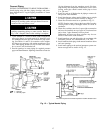
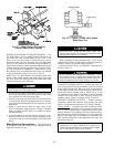
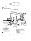
Fig. 15 — Water Piping, Oil Cooler to
Chilled Water Circuit (Typical)
Fig. 16 — Typical 17/19EX Utility Vessel
Relief Valve Tee
20