


CARRIER COMFORT NETWORK INTERFACE — The
Carrier Comfort Network (CCN) communication bus wiring
is supplied and installed by the electrical contractor (if re-
quired by jobsite prints). It consists of shielded, 3-conductor
cable with drain wire.
The system elements are connected to the communication
bus in a daisy chain arrangement. The positive pin of each
system element communication connector must be wired to
the positive pins of the system element on either side of it.
The negative pins must be wired to the negative pins. The
signal ground pins must be wired to the signal ground pins.
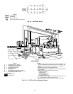
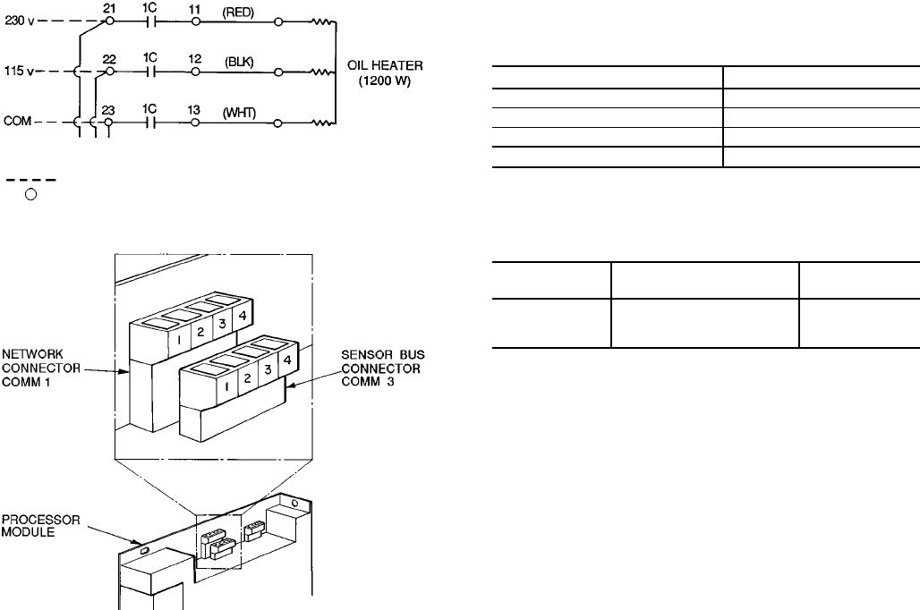
See Fig. 23 for location of the CCN network connector
(COMM1) on the processor module.
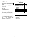
NOTE: Conductors and drain wire must be 20 AWG
(American Wire Gage) minimum stranded, tinned copper. In-
dividual conductors must be insulated with PVC, PVC/
nylon, vinyl, Teflon, or polyethylene. An aluminum/ poly-
ester 100% foil shield and an outer jacket of PVC, PVC/
nylon, chrome vinyl, or Teflon with a minimum operating
temperature range of −4 F to 140 F (−20 C to 60 C) is
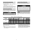
required. See table below for cables that meet the
requirements.
MANUFACTURER CABLE NO.
Alpha 2413 or 5463
American A22503
Belden 8772
Columbia 02525
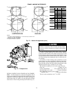
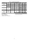
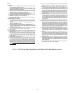
When connecting the CCN communication bus to a sys-
tem element, a color code system for the entire network is
recommended to simplify installation and checkout. The fol-
lowing color code is recommended:
SIGNAL TYPE
CCN BUS CONDUCTOR
INSULATION COLOR
COMM1 PLUG
PIN NO.
+ Red 1
Ground White 2
− Black 3
If a cable with a different color scheme is selected, a
similar color code should be adopted for the entire network.
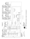
At each system element, the shields of its communication
bus cables must be tied together. If the communication bus
is entirely within one building, the resulting continuous shield
must be connected to ground at only one single point. See
Fig. 23. If the communication bus cable exits from one build-
ing and enters another, the shields must be connected to ground
at the lightning suppressor in each building where the cable
enters or exits the building (one point only).
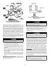
To connect the 17/19EX chiller to the network, proceed
as follows (Fig. 23):
1. Cut power to the PIC (Product Integrated Control) panel.
2. Remove the COMM1 plug from the processor module.
3. Cut a CCN wire and strip the ends of the RED, WHITE,
and BLACK conductors.
4. Using a wirenut, connect the drain wires together.
5. Insert and secure the RED wire to Terminal 1 of the
COMM1 plug.
6. Insert and secure the WHITE wire to Terminal 2 of the
COMM1 plug.
7. Insert and secure the BLACK wire to Terminal 3 of the
COMM1 plug.
8. Attach the COMM1 plug back onto the processor
module.
9. Mount a terminal strip in a convenient location.
10. Connect the opposite ends of each conductor to separate
terminals on the terminal strip.
11. Attach the CCN Network wiring:
a. Connect the RED wire to the matching location on
the terminal strip.
b. Connect the WHITE wire to the matching location
on the terminal strip.
c. Connect the BLACK wire to the matching location
on the terminal strip.
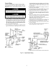
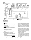
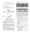
LEGEND
Field Wiring
Power Panel Component Terminal
Fig. 21 — Oil Heater and Control Power Wiring
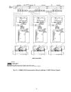
Fig. 22 — Carrier Comfort Network
Communication Bus Wiring
27