


RIG MACHINE COMPONENTS — Refer to instructions
on page 5, Fig. 6-8, and Carrier certified drawings for ma-
chine component disassembly.
IMPORTANT: Only a qualified service technician should
disassemble and reassemble the machine. After reas-
sembly, the machine must be dehydrated and leak tested.
When rigging components separately, the open drive
(17EX) motor must be removed to avoid overturning.
Do not attempt to disconnect flanges while the machine
is under pressure. Failure to relieve pressure can result
in personal injury or damage to the unit.
Before rigging the compressor, disconnect the wires
leading from the power panel to the control center at the
power panel.
NOTE: Wiring for sensors must be disconnected. Label each
wire before removal (see Carrier certified drawings).
Detach all transducer and sensor wires at the sensor, then
clip all wire ties necessary to remove the wires from the heat
exchangers.
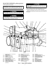
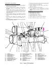
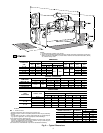
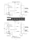
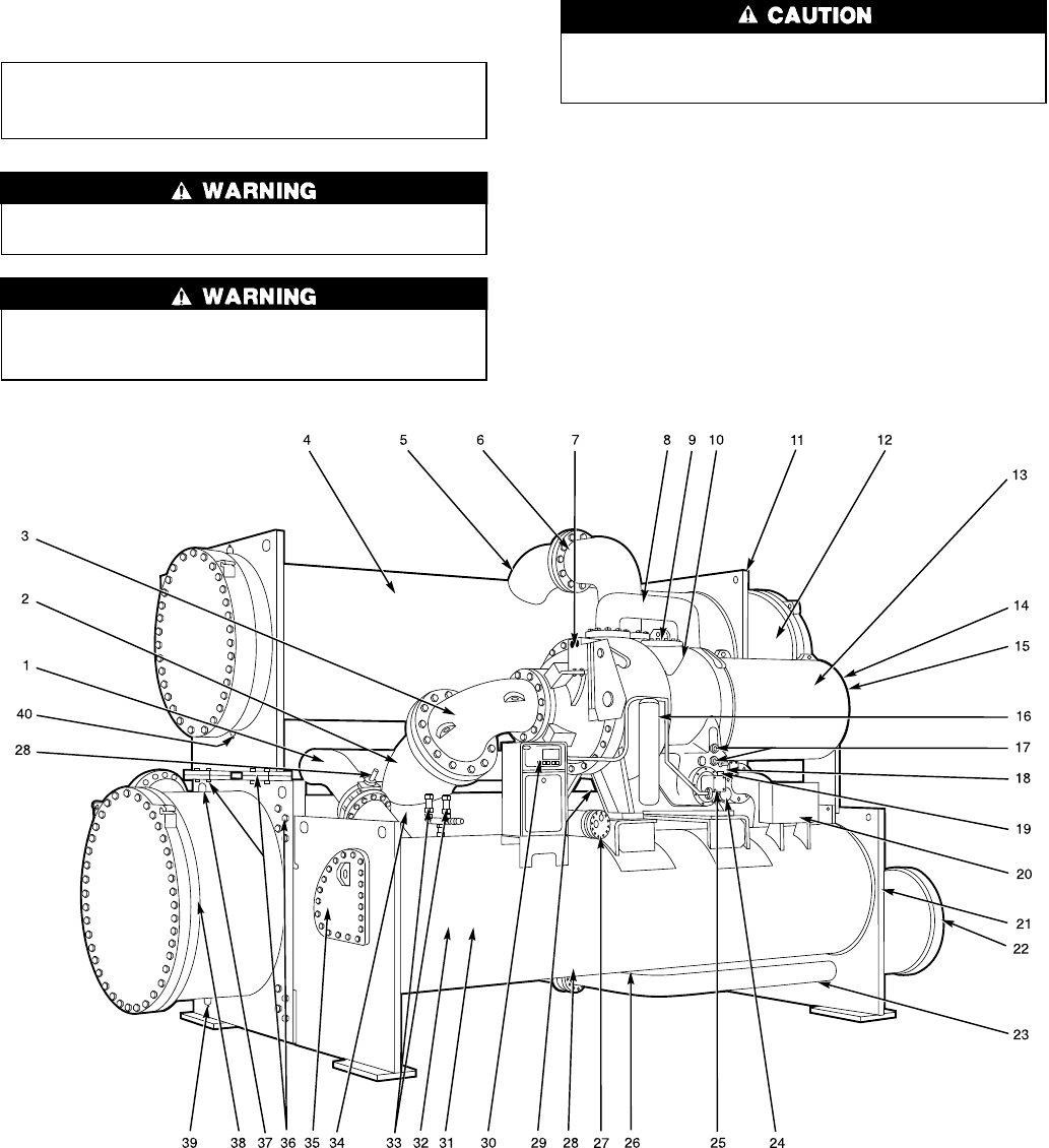
19EX
LEGEND
1—Refrigerant Liquid Line to Economizer/
Storage Vessel
2—Cooler Suction Pipe
3—Compressor Suction Elbow
4—Condenser
5—Condenser Discharge Pipe
6—Compressor Discharge Elbow
7—Guide Vane Actuator
8—Economizer Gas Line to Compressor
9—Gear Inspection Cover
10 — 2-Stage Hermetic Compressor
11 — Condenser Waterbox Vent (Not Shown)
12 — Condenser Marine Waterbox
13 — Hermetic Compressor Motor
14 — Compressor Motor Terminal Box
(Not Shown)
15 — Motor Sight Glass (Not Shown)
16 — Oil Filter
17 — Oil Level Sight Glasses (2)
18 — Cooler Relief Valves (Not Shown)
19 — Oil Heater (Not Shown)
20 — Auxiliary Power Panel
(Field Wiring Terminals)
21 — Pumpdown Unit (Not Shown)
22 — Low-Side Float Box Cover
23 — Refrigerant Liquid Line to Cooler
24 — Oil Drain and Charging Valve
25 — Oil Pump
26 — Refrigerant Charging/Service
Valve 10 (Not Shown)
27 — Oil Cooler
28 — Isolation Valves (Not Shown)
29 — Refrigerant Filter Drier
30 — Local Interface Display Control Panel
31 — Economizer/Storage Vessel
32 — Rigging Guide (Not Shown)
33 — Economizer/Storage Vessel
Relief Valves
34 — Cooler
35 — High-Side Float Box Cover
36 — Take-Apart Connections
37 — Cooler Waterbox Vent
38 — Cooler Marine Waterbox
39 — Cooler Waterbox Drain
40 — Condenser Waterbox Drain
Fig.2—Typical 19EX Installation
4