


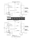
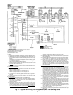
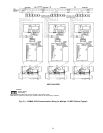
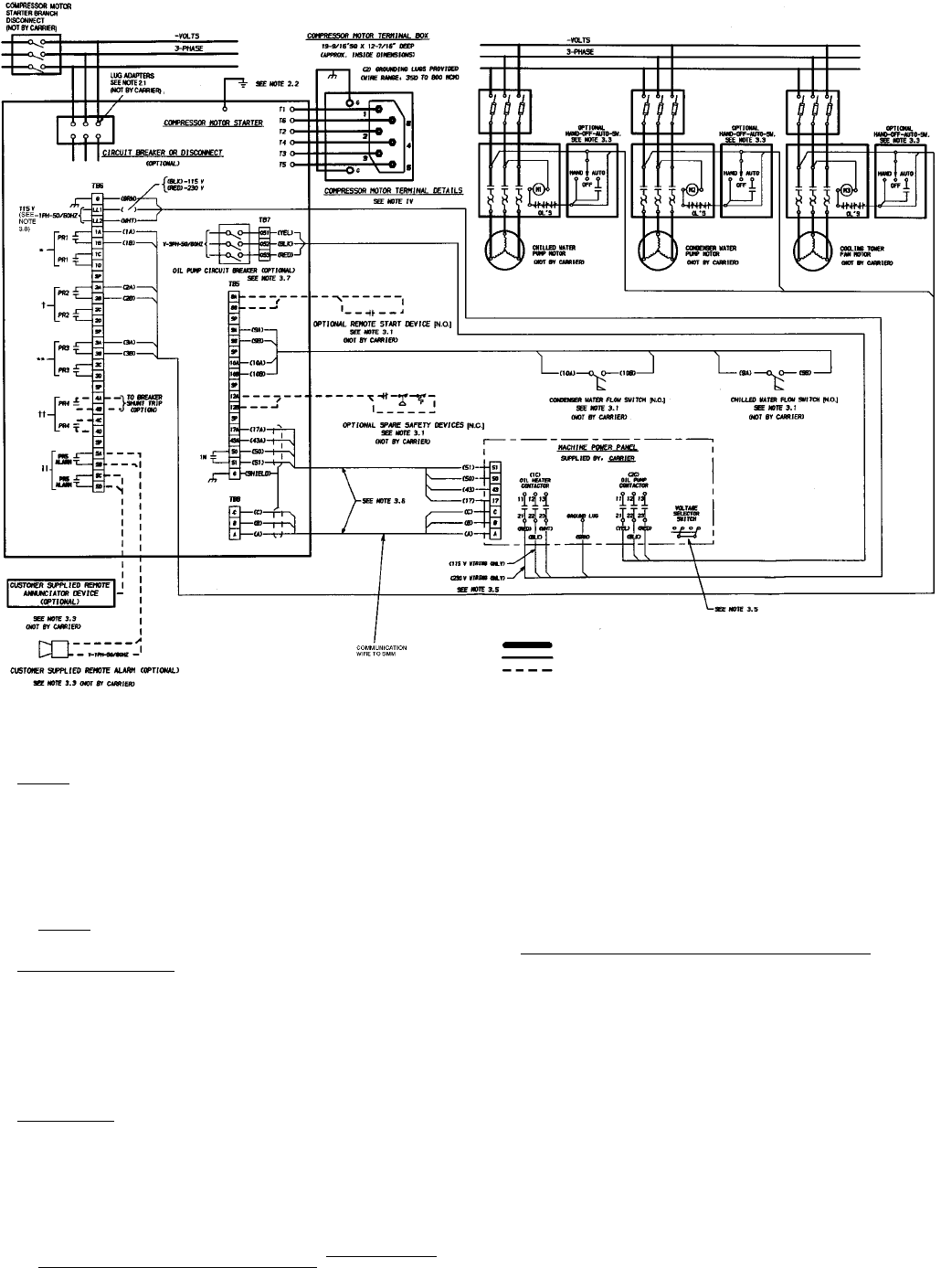
*Indicates chilled water pump control contacts or run status contacts.
†Indicates condenser water pump control contacts.
**Indicates tower fan relay contacts.
††Indicates circuit breaker shunt trip contacts.
Indicates remote alarm contacts.
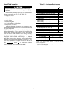
LEGEND
Required Power Wiring
Required Control Wiring
Options Wiring
SMM — Starter Management Module
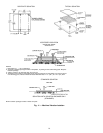
NOTES:
I. GENERAL
1.0 Starters shall be designed andmanufactured inaccordance with Carrier Engineer-
ing Requirement Z-375.
1.1 Allfield-suppliedconductors,devices,field-installationwiring,andterminationofcon-
ductorsand devices,must bein compliancewith allapplicable codes andjob speci-
fications.
1.2 The routing of field-installed conduit and conductors and the location of field-
installeddevicesmustnotinterfere withequipmentaccessorthereading, adjusting,
or servicing of any component.
1.3 Equipment, installation, and all starting and control devices must comply with de-
tails in equipment submittal drawings and literature.
1.4 Contactsand switches areshown in the position theywould assume with the circuit
deenergized and the chiller shut down.
1.5 WARNING — Do not use aluminum conductors.
1.6 Installer is responsible for any damage caused by improper wiring between starter
and machine.
II. POWER WIRING TO STARTER
2.0 Power conductor rating must meet minimum unit nameplate voltageand compres-
sor motor RLA.
When (3) conductors are used:
Minimum ampacity per conductor = 1.25 x compressor RLA
When (6) conductors are used for Wye-Delta starting:
Minimum ampacity per conductor = 0.721 x compressor RLA
2.1 Lug adapters may be required if installation conditions dictate that conductors be
sized beyond the minimum ampacity required. Contact starter supplier for lug
information.
2.2 Compressor motor and controls must be grounded by using equipment grounding
lugs provided inside starter enclosure.
III. CONTROL WIRING
3.0 Field supplied control conductors to be at least 18 AWG or larger.
3.1 Chilled water and condenser water flow switch contacts, optional remote start de-
vice contacts and optional spare safety device contacts must have 24 vdc rating.
Max current is 60 ma, nominal current is 10 ma. Switches with gold plated bifur-
cated contacts are recommended.
3.2 Removejumperwire between12Aand 12Bbefore connectingauxiliary safeties be-
tween these terminals.
3.3 Pilot relays can control cooler and condenser pump and tower fan motor contactor
coilloads rated10amps at115 vacupto 3amps at600 vac.Controlwiring required
for Carrier to start pumps and tower fan motors must be provided to assure
machine protection. If primary pump and tower fan motor are controlled by other
means, also provide a parallel means for control by Carrier.Do not use starter con-
trol transformer as the power source for pilot relay loads.
3.4 Do not route control wiring carrying 30 v or less within a conduit which has wires
carrying 50 v or higher or along side wires carrying 50 v or higher.
3.5 Voltageselectorswitchinmachinepowerpanel isfactorysetfor115vcontrolpower
source. Do not use the 230 v position. If this switch is set to 230 v position, the oil
heater will not operate.
3.6 Controlwiring cablesbetween starter andpower panelmust be shieldedwith mini-
mum rating of 600 v, 80 C ground shield at starter. WiresA,B, and C are commu-
nication wires and must be run in a separate cable.
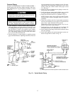
3.7 If optional oil pump circuit breaker is not supplied within the starter enclosure as
shown, it must be located within sight of the machine with wiring routed to suit.
3.8 Voltageto terminals LL1 and LL2 comes from acontrol transformer in a starter built
to Carrier specifications. Do not connect an outside source of control power to the
compressor motor starter (terminals LL1 and LL2). An outside power source will
producedangerousvoltage atthe linesideof thestarter,becausesupplyingvoltage
at the transformer secondary terminals produces input level voltage at the trans-
former primary terminals.
IV. POWER WIRING BETWEEN STARTER AND COMPRESSOR MOTOR
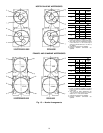
4.0 Lowvoltage (600 v orless) compressor motors have (6),
5
⁄
8
in. terminal studs (lead
connectors not suppliedby Carrier). Either 3 or 6 leads must be run between com-
pressor motor and starter, depending on type of motor starter employed. If only 3
leads are required, jumper motor terminals as follows: 1 to 6, 2 to 4, 3 to 5. Center
tocenterdistancebetweenterminalsis2
15
⁄
16
inches.Compressormotorstartermust
havenameplatestamped astoconforming withCarrier requirementZ-375.Medium
voltage (over 600 v) compressor motors have (3) terminals. Connections out ofter-
minals are 3 in. long stranded wire pigtails, #4 AWG, strand wire for all medium
voltage motor sizes. Distance between terminal is 7
9
⁄
16
inches. Use suitable splice
connectorsandinsulationforhighvoltagealternatingcurrentcableterminations(these
items are not supplied by Carrier). Compressor motor starter must have nameplate
stamped as to conforming with Carrier requirement Z-375.
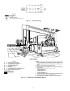
4.1 When more than one conduit is used to run conductors from starter to compressor
motor terminal box, one conductor from each phase must be in each conduit to
prevent excessive heating. (e.g., conductors to motor terminals 1, 2 and 3 in one
conduit, and those to 4, 5 and 6 in another.)
4.2 Compressor motor power connections can be made through top, top rear or sides
ofcompressormotor terminalboxusingholes cutbycontractor tosuitconduit. Flex-
ible conduit should be used forthe last few feet to the terminal box for unit vibration
isolation. Use of stress cones or 12 conductors larger than 500 MCM may require
an oversize (special) motor terminal box (not supplied by Carrier). Lead connec-
tions between 3-phase motors and their starters mustnot beinsulated until Carrier
personnel have checked compressor and oil pump rotations.
4.3 Compressormotor frame to be grounded in accordance with the National Electrical
Code (NFPA-70) and applicable codes. Means for grounding compressor motor is
a pressure connector for #4 to 500 MCM wire, supplied and located in the back
lower left side corner of the compressor motor terminal box.
4.4 Do not allow motor terminals to support weight of wire cables. Use cable supports
and strain reliefs as required.
4.5 Usebackupwrenchwhentighteningleadconnectorstomotorterminalstuds.Torque
to 45 lb-ft max.
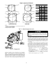
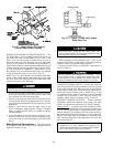
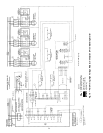
Fig. 17 — Typical Field Wiring (Low-Voltage Motors) with Free-Standing Starter
23