


NOTES:
I GENERAL
1.0 Starters shall be designed and manufactured in accordance with
Carrier Engineering requirement Z-375.
1.1 All field-supplied conductors, devices and the field-installation wiring,
termination of conductors and devices, must be in compliance with all
applicable codes and job specifications.
1.2 The routing of field-installedconduit and conductors and the location of
field-installed devices, must not interfere with equipment access of the
reading, adjusting, or servicing of any component.
1.3 Equipmentinstallation and all starting and control devices must comply
with details in equipment submittal drawings and literature.
1.4 Contacts and switches are shown in the position they would assume
with the circuit deenergized and the chiller shut down.
1.5 WARNING: Do not use aluminum conductors.
1.6 Installer is responsible for any damage caused by improper wiring be-
tween starter and machine.
II POWER WIRING TO STARTER
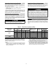
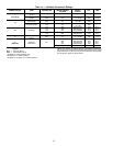
2.0 Power conductor rating must meet minimum unit nameplate voltage
and compressor motor RLA (rated load amps). When (3) conductors
are used:
Minimum ampacity per conductor =1.25 x compressor RLA
When (6) conductors are used:
Minimum ampacity per conductor =0.721 x compressor RLA.
2.1 Lugadapters may be required if installation conditions dictate that con-
ductorsbe sizedbeyond theminimum ampacityrequired. Contact starter
supplier for lug information.
2.2 Compressor motor and controls must be grounded by using equip-
ment grounding lugs provided inside starter enclosure.
III CONTROL WIRING
3.0 Fieldsupplied controlconductors to be at least 18AWG (AmericanWire
Gage), or larger.
3.1 Chilled water and condenser water flow switch contacts, optional re-
mote start device contacts, and optional spare safety device contacts
must have 24 vdc rating. Maximum current is 60 ma, nominal current
is 10 ma. Switches with gold plated bifurcated contacts are
recommended.
3.2 Removejumper wirebetween 12A and 12B before connecting auxiliary
safeties between these terminals.
3.3 Maximumload on pilot relays is 10 amps. Pilot relays can control cooler
and condenser pump and tower fan motor contactor coil loads rated up
to 10 amps at 115 vac or up to 3 amps at 600 vac. Control wiring re-
quired for Carrier to start pumps and tower fan motors must be pro-
vided to assure machine protection. If primary pump and tower motor
control is by other means, also provide a parallel means for control by
Carrier. Do not use starter control transformer as the power source for
pilot relay loads.
3.4 Do not route control wiring carrying 30 v or less within a conduit which
has wires carrying 50 v or higher or along side wires carrying 50 v or
higher.
3.5 Voltage selector switch in machine power panel is factory set for
115 v control and oil heater power source. The 230 v position is not
used. If switch is set to 230 v position, oil heater will not operate.
3.6 Controlwiringcables between starterand power panelmust be shielded
with minimum rating of 600 v, 80 C. Ground shield at starter. Wires A,
B,and C are communication wiresand must be run ina separate cable.
3.7 If optional oil pump circuit breaker is not supplied within the starter en-
closure as shown, it must be located within sight of the machine with
wiring routed to suit.
3.8 Voltage to terminals LL1 and LL2 comes from a control transformer in
astarter built toCarrier specifications. Donot connect anoutside source
of control power to the compressor motor starter (terminals LL1 and
LL2). An outside power source will produce dangerous voltage at the
line side of the starter, because supplying voltage at the transformer
secondaryterminals produces input level voltageat the transformer pri-
mary terminals.
IV POWER WIRING BETWEEN STARTER AND COMPRESSOR MOTOR
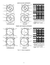
4.0 Medium voltage (over 600 volts) hermetic compressor motors have
3 terminals. Use no. 4 AWG strand wires for all medium and high volt-
age hermetic motors. Distance between terminal is 7
9
⁄
16
inches. Use
suitable splice connectors and insulation for high-voltage alternating
current cable terminations (these items are not supplied by Carrier).
Compressor motor starter must have nameplate stamped as to con-
forming with Carrier requirement Z-375. Medium voltage open motors
have lug terminations (see certified drawings for size).
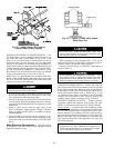
4.1 When more than one conduit is used to run conductors from starter to
compressor motor terminal box, one conductor from each phase must
be in each conduit, to prevent excessive heating, (e.g., conductors to
motor terminals 1, 2, and 3 in one conduit, and those to 1, 2, and 3 in
another).
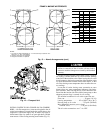
4.2 Compressor motor power connections can be made through top, top
rear, or sides of compressor motor terminal box by using holes cut by
contractor to suit conduit. Flexible conduit should be used for the last
few feet to the terminal box for unit vibration isolation. Use of stress
cones may require an oversize (special) motor terminal box (not sup-
plied by Carrier).
4.3 Compressor motor frame to be grounded in accordance with the Na-
tionalElectricalCode (NFPA-70)andapplicable codes.Meansfor ground-
ing compressor motor is a no. 4 AWG, 500 MCM pressure connector,
supplied and located in the lower left side corner of the compressor
motor terminal box.
4.4 Do not allow motor terminals to support weight of wire cables, use
cable supports and strain reliefs as required.
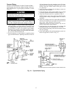
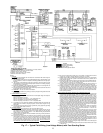
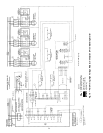
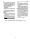
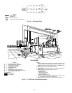
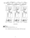
Fig. 18 — Field Wiring (High Voltage Motors) with Optional Free-Standing Starter (cont)
25