


COMPONENT DISASSEMBLY
To Separate Compressor from the Machine
1. Make sure to check that the machine is at atmospheric
pressure before disassembly.
2. Since the center of gravity is high on 17EX machines,
the motor MUST be removed before rigging the
machine.
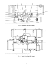
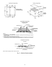
3. Suction elbow should be rigged separately (Fig. 6,
Item 2). Place slings around the elbow and attach to the
hoist. Remove bolting at flanges, (Fig. 6, Items 1 and 3).
Detach the elbow.
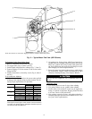
4. Unbolt discharge flange to the condenser at flange
(Fig. 8, Item 3). Cut copper lines (Fig. 6, Items 7, 8,
and 9).
5. Disconnect and detach the economizer vent line
(Fig. 8, Item 4). Unbolt the line at flange (Fig. 8,
Item 2).
6. On 19EX machines, disconnect the motor cooling drain
line at flange (Fig. 8, Item 5).
7. Disconnect wiring to the control center and power panel.
8. Connect rigging to the compressor.
9. Unbolt compressor from the utility vessel (Fig. 7,
Items 2, 4, and 5).
10. Hoist the compressor off of the unit.
11. If the compressor is to be transported or set down,
the base should be bolted to sections of 4 in.x6in.
lumber.
To Separate Condenser from the Machine
1. Unbolt flange (Fig. 6, Item 3).
2. Unbolt flange (Fig. 6, Item 4).
3. Cut copper pipe (Fig. 6, Item 7).
4. Unbolt hot flange (Fig. 7, Item 1).
5. Connect rigging to all corners of the condenser.
6. Unbolt condenser feet (Fig. 8, Items 1 and 6).
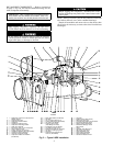
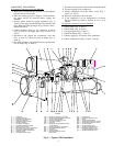
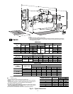
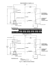
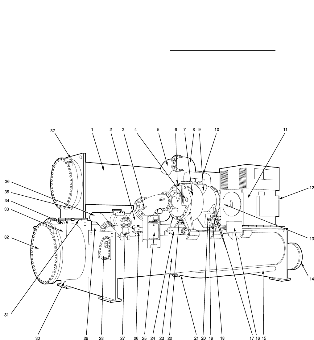
LEGEND
1—Condenser
2—Cooler Suction Pipe
3—Compressor Suction Elbow
4—Guide Vane Actuator
5—Condenser Discharge Pipe
6—Oil Filter (Hidden)
7—Two-Stage Compressor
8—Compressor Discharge Elbow
9—Gear Inspection Cover
10 — Economizer Gas Line to Compressor
11 — Open Drive Compressor Motor
12 — Compressor Motor Terminal Box
13 — Coupling Guard
14 — Low-Side Float Box Cover
15 — Refrigerant Liquid Line to Cooler
16 — Power Panel (Field Wiring Terminals)
17 — Oil Level Sight Glasses
18 — Oil Drain and Charging Valve
19 — Oil Heater (Hidden)
20 — Oil Pump
21 — Refrigerant Charging/Service Valve
10 (Not Shown)
22 — Cooler Relief Valves (Not Shown)
23 — Economizer/Storage Vessel
24 — Oil Cooler
25 — Control Center
26 — Economizer/Storage Vessel
Relief Valves
27 — Pumpout Unit
28 — High Side Float Box Cover
29 — Cooler
30 — Cooler Waterbox Drain
31 — Take-Apart Connections (Typical)
32 — Cooler Marine Waterbox Cover
33 — Cooler Waterbox
34 — Cooler Waterbox Vent
35 — Condenser Waterbox Drain
36 — Refrigerant Liquid Line to
Economizer/Storage Vessel
37 — Condenser Waterbox Vent
Fig.3—Typical 17EX Installation
5