


17-2
Catalyst 3560 Switch Software Configuration Guide
OL-8553-06
Chapter 17 Configuring STP
Understanding Spanning-Tree Features
• Spanning-Tree Interoperability and Backward Compatibility, page 17-10
• STP and IEEE 802.1Q Trunks, page 17-10
• VLAN-Bridge Spanning Tree, page 17-10
For configuration information, see the “Configuring Spanning-Tree Features” section on page 17-11.
For information about optional spanning-tree features, see Chapter 19, “Configuring Optional
Spanning-Tree Features.”
STP Overview
STP is a Layer 2 link management protocol that provides path redundancy while preventing loops in the
network. For a Layer
2 Ethernet network to function properly, only one active path can exist between
any two stations. Multiple active paths among end stations cause loops in the network. If a loop exists
in the network, end stations might receive duplicate messages. Switches might also learn end-station
MAC addresses on multiple Layer 2 interfaces. These conditions result in an unstable network.
Spanning-tree operation is transparent to end stations, which cannot detect whether they are connected
to a single LAN segment or a switched LAN of multiple segments.
The STP uses a spanning-tree algorithm to select one switch of a redundantly connected network as the
root of the spanning tree. The algorithm calculates the best loop-free path through a switched Layer
2
network by assigning a role to each port based on the role of the port in the active topology:
• Root—A forwarding port elected for the spanning-tree topology
• Designated—A forwarding port elected for every switched LAN segment
• Alternate—A blocked port providing an alternate path to the root bridge in the spanning tree
• Backup—A blocked port in a loopback configuration
The switch that has all of its ports as the designated role or as the backup role is the root switch. The
switch that has at least one of its ports in the designated role is called the designated switch.
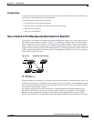
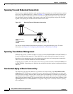
Spanning tree forces redundant data paths into a standby (blocked) state. If a network segment in the
spanning tree fails and a redundant path exists, the spanning-tree algorithm recalculates the
spanning-tree topology and activates the standby path. Switches send and receive spanning-tree frames,
called bridge protocol data units (BPDUs), at regular intervals. The switches do not forward these frames
but use them to construct a loop-free path. BPDUs contain information about the sending switch and its
ports, including switch and MAC addresses, switch priority, port priority, and path cost. Spanning tree
uses this information to elect the root switch and root port for the switched network and the root port and
designated port for each switched segment.
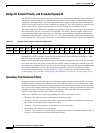
When two ports on a switch are part of a loop, the spanning-tree port priority and path cost settings
control which port is put in the forwarding state and which is put in the blocking state. The spanning-tree
port priority value represents the location of a port in the network topology and how well it is located to
pass traffic. The path cost value represents the media speed.
Note In Cisco IOS Release 12.2(18)SE and later, the default is for the switch to send keepalive messages (to
ensure the connection is up) only on interfaces that do not have small form-factor pluggable (SFP)
modules. You can use the [no] keepalive interface configuration command to change the default for an
interface.