


20-9
Catalyst 3560 Switch Software Configuration Guide
OL-8553-06
Chapter 20 Configuring Flex Links and the MAC Address-Table Move Update Feature
Configuring Flex Links and the MAC Address-Table Move Update
Configuring Flex Links
Beginning in privileged EXEC mode, follow these steps to configure a pair of Flex Links:
To disable a Flex Link backup interface, use the no switchport backup interface interface-id interface
configuration command.
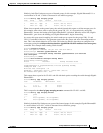
This example shows how to configure an interface with a backup interface and to verify the
configuration:
Switch# configure terminal
Switch(conf)# interface gigabitethernet0/1
Switch(conf-if)# switchport backup interface gigabitethernet0/2
Switch(conf-if)# end
Switch# show interfaces switchport backup
Switch Backup Interface Pairs:
Active Interface Backup Interface State
------------------------------------------------------------------------
GigabitEthernet0/1 GigabitEthernet0/3 Active Standby/Backup Up
Vlans Preferred on Active Interface: 1-3,5-4094
Vlans Preferred on Backup Interface: 4
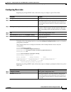
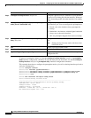
Beginning in privileged EXEC mode, follow these steps to configure a preemption scheme for a pair of
Flex Links:
Command Purpose
Step 1
configure terminal Enter global configuration mode.
Step 2
interface interface-id Specify the interface, and enter interface configuration
mode. The interface can be a physical Layer 2 interface or
a port channel (logical interface). The port-channel range
is 1 to 48.
Step 3
switchport backup interface interface-id Configure a physical Layer 2 interface (or port channel)
as part of a Flex Link pair with the interface. When one
link is forwarding traffic, the other interface is in standby
mode.
Step 4
end Return to privileged EXEC mode.
Step 5
show interfaces [interface-id] switchport backup Verify the configuration.
Step 6
copy running-config startup config (Optional) Save your entries in the switch startup
configuration file.
Command Purpose
Step 1
configure terminal Enter global configuration mode.
Step 2
interface interface-id Specify the interface, and enter interface configuration
mode. The interface can be a physical Layer 2 interface or
a port channel (logical interface). The port-channel range
is 1 to 48.