19
Chapter 1 Setup
Part Names and Functions
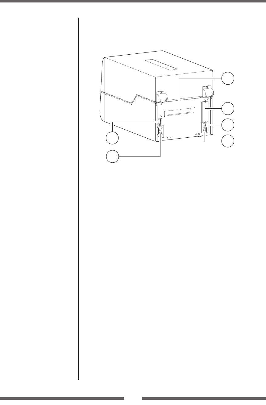
Rear View
1
2
3
4
5
6
1
Power switch
The is the power switch for the printer.
2
Power cord inlet
The connector of the enclosed power cord is connected here.
3
Fanfold paper insertion slot
If you want to use fanfold paper, insert the media into this slot from
outside the printer.
4
Option interface
Optional interface board can be installed by removing the interface
cover. Contact your retailer if you want to use the option interface.
5
USB interface (USB2.0)
This receives USB transmission of data from a host computer.
6
Ethernet interface
Data from host computer is received via wired LAN communication.
NOTE: Do not connect the USB cable to the wired LAN connector.
Doing so may damage the connector.
Replacing the Interface Board
(p.89)
USB Interface (p.76)
Connection to Power (p.20)
Ethernet Interface (p.77)
Power ON/OFF (p.22)


