


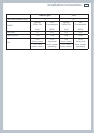
9
1
2
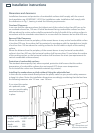
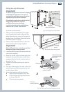
65
mm
833 mm
0
+ 25
min 210 mm
max 235 mm
(depending on feet adjustment)
898 mm (product width)
Installation instructions
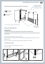
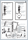
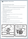
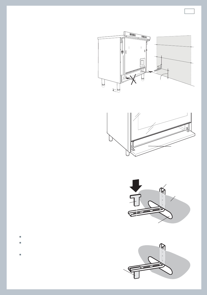
Fitting the anti-tilt bracket
Important!
To restrain the appliance and prevent it tipping
accidentally, fit a bracket to its rear to fix it
securely to the wall. Make sure you also fit the
supplied lock pin to the anti-tilt bracket.
If installing the cooker above a plinth (without
fitting the adjustable feet), revise the
installation dimensions accordingly
considering that the feet have the following
measures: min 155 mm - max 180 mm.
To fit the anti-tilt bracket:
1
After you have located where the cooker
is to be positioned, mark on the wall the
place where the two screws of the anti-tilt
bracket have to be fitted. Please follow the
indications given in Fig10a.
2
Drill two 8 mm diameter holes in the wall
and insert the plastic plugs supplied.
Important!
Before drilling the holes, check that you will not
damage any pipes or electrical wires.
3
Loosely attach the anti-tilt bracket with the
two screws supplied.
4
Move the cooker to the wall and adjust the
height of the anti-tilt bracket so that it can
engage in the slot on the cooker’s back, as
shown in Fig.10a.
5
Tighten the screws attaching the anti-tilt
bracket.
6
Push the cooker against the wall so that the
anti-tilt bracket is fully inserted in the slot
on the cooker’s back.
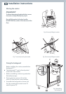
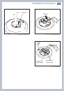
7
Access the bracket and fit the lock pin;
Open the pivoting panel (Fig. 10b).
Fit the lock pin through the bracket,
as shown (Fig.10c).
Close the pivoting panel.
Fig. 10a Fitting the anti-tilt bracket
Fig. 10b Opening the pivoting panel
Fig. 10c Fitting the lock pin through the bracket
Pivoting
panel
Anti-tilt bracket
attached on the
rear wall
Cooker’s
back
Lock pin
Slot on the
cooker’s back
Lock pin
correctly tted