


10
Installation instructions
Connecting the cooker to the gas supply
The gas connection must be carried out by an authorised person according to the relevant
standards.
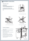
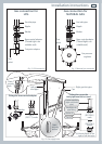
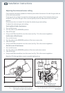
Before connecting the appliance to the gas main, mount the brass conical adaptor onto the gas
inlet pipe, upon which the washer has been placed (see Fig.s 11-12 following).
Conical adaptor and washer are supplied with the appliance (packed with conversion kit for use
with Natural gas or LPG).
This appliance is suitable for use with Natural gas or LPG. (Check the “gas type” sticker attached
to the appliance).
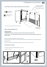
For Natural gas, connect the gas supply to the gas pressure regulator which is supplied with
the appliance (Fig.12). Adjust the regulator to obtain a test point pressure of 1 kPa with the two
semi-rapid burners operating at the maximum.
For LPG, connect the gas supply to the test point adaptor which is supplied with the appliance
(Fig.11). Ensure that the supply pressure is regulated to 2.75 kPa.
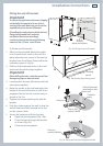
The connection must be made at the rear of appliance (left or right); the pipe is not to cross the
cooker.
Close off the unused inlet with the cap and sealing washer supplied (Fig. 13).
IMPORTANT: Use two spanners to tighten or loosen the connecting pipe (Fig.13).
Installation with a flexible hose assembly
If this appliance has to be installed with a hose assembly, the installer shall refer to the network
operator or gas supplier for confirmation of the gas type, if in doubt.
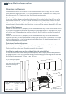
When used with a flexible hose, the connector on the wall should be between 450 mm to 500
mm from the floor and 200 mm to 300 mm from the left-hand side of the appliance as viewed
from the front. The hose connection on the appliance shall face downwards.
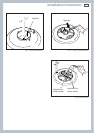
It is important that the hose does not come in contact with the metal of the appliance and is
secured as per appropriate gas installation codes. A chain 80% of the length of the flexible gas
hose must be used to prevent stress being applied to the hose. The chain should be attached
securely to the product where shown (see Fig.13), and on the wall.
Flexible hose assemblies should be AS/NZS 1869 Class B or Class D certified. The thread
connection shall be Rp ½ ” (ISO 7-1) male.
Important!
After connection the installer must check that the hose is not kinked, subjected to abrasion or permanently
deformed. The installer must check also that the hose is not near or in contact with any hot surfaces.
The hose assembly shall be as short as practicable and comply with relevant AS5601 / NZS5261
requirements.