


Earth/Ground Tester
Procedure of Measurements
37
Errors of the current transformer can be corrected as described in “Correcting
Clip-on Transformer Error”.
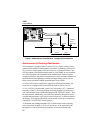
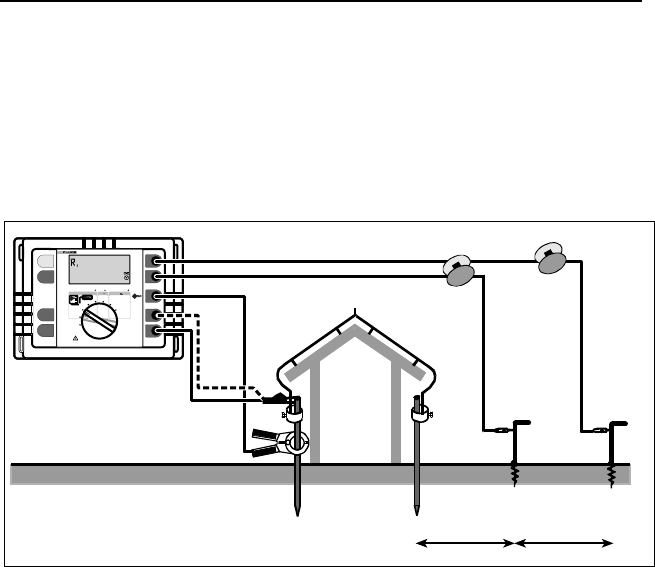
3-pole/4-pole Measurement of Single Earth Electrode Re-
sistances
See Figure 12.
R
RA
R
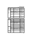
Earth/Ground Resistance 300 k
AC
Resistance
300 k
DC Low Resistance 3k
CHANGE
ITEM
SELECT
START
TEST
DISPLAY
MENU
H/C2
S/P2
ES/P1
E/C1
4 POLE
3 POLE
4 POLE
2 POLE
2 POLE
4 POLE
OFF
3 POLE
EARTH / GROUND TESTER
1625
Auxiliary
earth
electrode
Probe
Earth
electrode
4 Pole
>20 m >20 m
edw015.eps
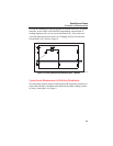
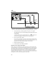
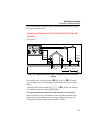
Figure 12. 3-pole/4-pole Measurement of Single Earth Electrode Resis-
tances
Turn central rotary switch to position "A RE 3pole" or "A RE 4pole".
The instrument is to be wired according to picture and notices given on the
display.
A flashing of the sockets symbols EFGH or A, points to an incorrect
or incomplete connection of the measuring lead.
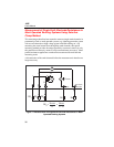
Fix clip-on transformer around the earth electrode to be measured.
Make sure that the clip-on transformation ratio set on the instrument corre-
sponds to the clip-on transformer used. Change settings if necessary (see
“Changing of all Data Settings with Personalised CODE”)