


1625
Users Manual
40
Accordingly, these equivalent resistances are displayed as:
li
U
R
meas
Ei
=
Therefore the earthing resistance R
E
of the pylon is determined as a parallel
circuit of the individual equivalent resistances:
4321
1111
1
EEEE
E
RRRR
R
+++
=
R
RA
R
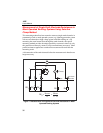
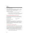
Earth/Ground Resistance 300 k
AC
Resistance
300 k
DC Low Resistance 3k
CHANGE
ITEM
SELECT
START
TEST
DISPLAY
MENU
H/C2
S/P2
ES/P1
E/C1
4
POLE
3
POLE
4
POLE
2
POLE
2
POLE
4
POLE
OFF
3
POLE
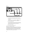
EARTH / GROUND TESTER
1625
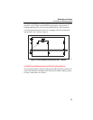
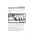
Auxiliary
earth
electrode
Probe
4 Pole
>20 m >20 m
edw016.eps
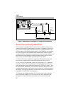
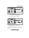
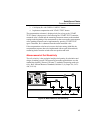
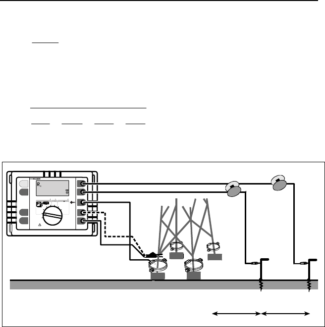
Figure 13. Measuring the Earthing Resistance without Disengaging the
Overhead Earth Wire
1. Turn central rotary switch to position “AR
E
3pole" or AR
E
4pole". The instrument is to be wired according to picture and notices
given on the display.
A flashing of the sockets symbols EFGH or B, points to an
incorrect or incomplete connection of the measuring lead.
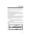
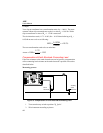
2. Apply current transformer to the pylon stub. Make sure that the trans-
formation ratio set on the instrument corresponds to the current trans-
former used. Change settings if necessary (see “Changing of All Data
Settings with Personalised CODE”)