


Earthing Resistance
Principle of Operation
79
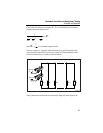
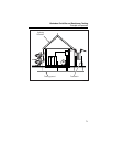
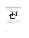
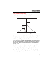
The Potential Gradient Area
Around every earth electrode a so called potential gradient area develops dur-
ing the flow of an electric current (see picture below).
U
U
S
U
E
E
40
60 m
edw058.eps
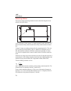
If the voltage between the earth electrode and a probe with a distance "a" from
the earth electrode is measured, the value increases less with increasing dis-
tance. Once the voltage does not increase, the probe is levelled to earth poten-
tial F
E
that is, outside the potential gradient area.
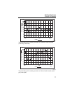
It is the soil resistivity that mainly affects the diameter of the potential gradient
area. This means the diameters in soils with a bad conductivity are correspond-
ingly wide (30 ... 60 m), soils with a good conductivity correspondingly nar-
row (10 ... 15 m).
Determining the probe- and auxiliary earth electrode resistance provides in-
formation about the size of a possible potential gradient area. High resistances
lead to correspondingly large gradient areas and vice versa. In this context it
has to be taken into account that soils with a good conductivity and corre-
spondingly small potential gradient areas result in a relatively steep voltage
shape and therefore in a relatively high step voltage. If necessary, such systems
have to undergo a potential check.