


45 SERIES GAS FRYERS SERVICE AND PARTS MANUAL
CHAPTER 1: SERVICE PROCEDURES
1-1
1.1 Functional Description
The 45 Series fryers contain a welded steel (stainless or cold rolled) frypot that is directly heated by
gas flames that are diffused evenly over its lower surface by ceramic targets.
The flames originate from orifices in a U-shaped burner manifold positioned beneath the frypot.
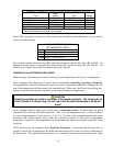
The orifice diameters differ for natural and propane gas as indicated in the table below (see Page 2-7
for a complete list of available orifices).
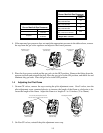
Gas Inches Millimeters
Natural 0.057 1.45
Propane 0.034 0.86
45 Series Orifice Sizes (0-1999 ft/609 m)
Gas flow to the manifold is regulated by an electromechanical gas valve. This series of fryers is
equipped with a 24-volt gas valve and all models use a pilot ignition system.
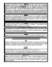
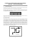
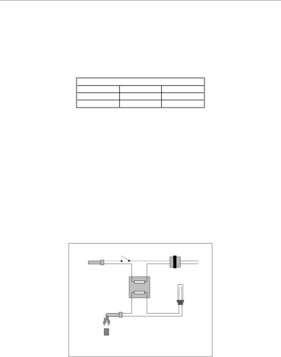
PILOT IGNITION SYSTEM
The pilot ignition system is comprised of the pilot orifice, pilot hood, and a thermopile. The pilot
serves two purposes. The first is to light the burner, the second is to heat the thermopile. In opera-
tion, the thermopile is in contact with the pilot flame and generates millivolts. The millivolt output
passes through a normally closed high-limit switch and energizes the gas valve pilot coil, which in
turn opens the pilot valve. If the pilot flame is extinguished, voltage is lost to the gas valve pilot coil
and the pilot valve closes. A separate 24-volt circuit, activated by the fryer ON/OFF switch, pro-
vides voltage through the thermostat or controller to the gas valve main coil, which opens the main
valve. The gas valve is constructed so that the main valve will not open if the pilot valve is not
open. The pilot flame must be manually lit (either with a match or with an optional built-in piezo
igniter) when the fryer is first placed into operation.
Controlling Thermostat
or
Controller
24 VAC
Transformer
High-Limit
Thermostat
Thermopile
Pilot Coil
Main Coil
Gas Valve
Line Voltage
Line Voltage
The Pilot System
ON/OFF
Switch
Pilot