6-3
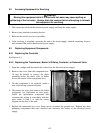
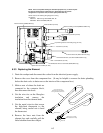
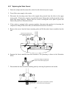
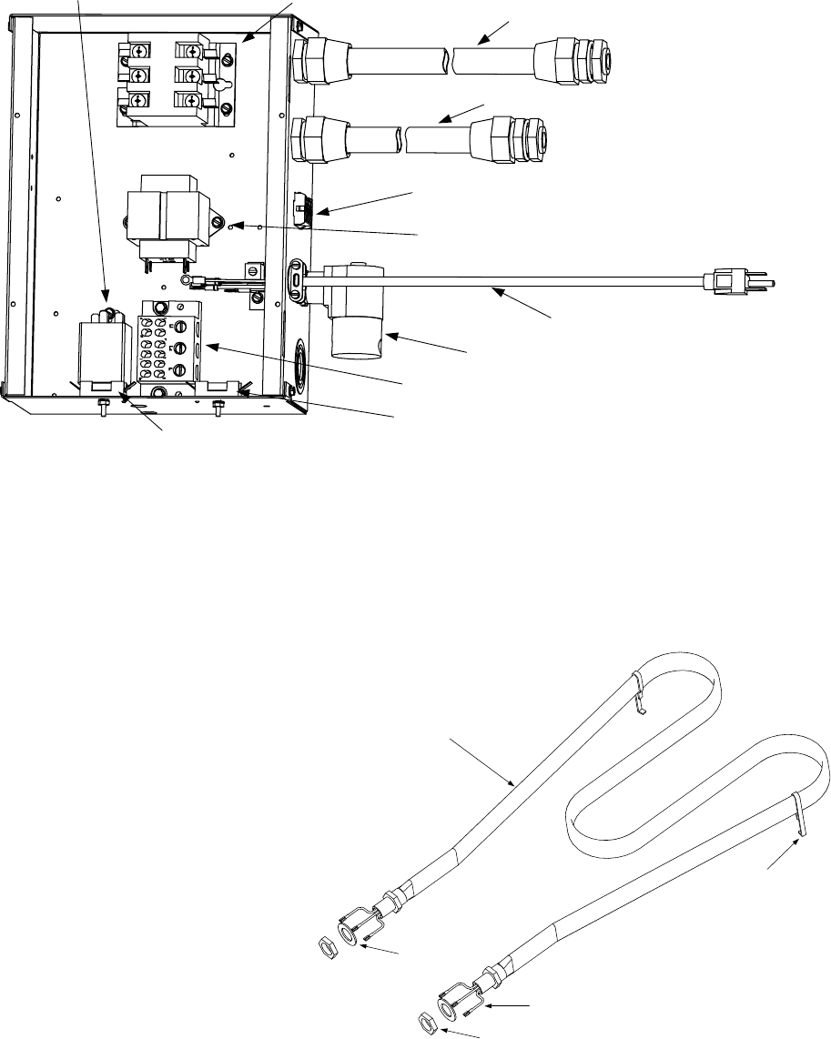
NOTE: This is a composite drawing for illustrative purposes only. It shows all parts
that may be mounted in the component box. Depending upon the specific
configuration of a particular unit, the actual parts present will vary.
NOTE: Refer to the following wiring diagrams for wiring
connections:
8050377J: 208V through 230V 8SMS, 8BC, 8C
8050462C: 480V/120V 8SMS, 8BC, 8C
Contactor Block (all units)
Basket Lift Wiring Conduit (8SMS and 8BC only)
Element Wiring Conduit (all units)
15-pin Wiring Harness Connecting Plug (all units)
Solenoid Valve (units with Autofill/Autoskim only)
120V Power Cord (480V/120V units only)
Transformer (all units)
Terminal Block (all units)
System Fuse and Holder (all units)
Basket Lift Fuse and Holder (8SMS, 8BC only)
Basket Lift Relay (8SMS, 8BC only)
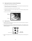
6.3.3 Replacing the Element
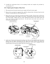
1. Drain the cookpot and disconnect the cooker from the electrical power supply.
2. Remove the cover from the component box. (It may be helpful to remove the drain plumbing
below the drain valve to better access the interior of the component box.)
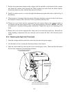
3. Make a note of where the leads are
connected to the contactor block,
then disconnect the leads.
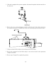
4. Cut the wire ties on the fiberglass
insulation and remove the
insulation from the element leads.
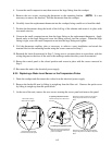
5. Cut the metal wire ties that secure
the high-limit thermostat to the
element, being careful not to bend
the thermostat.
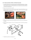
6. Remove the brass nuts from the
element legs and carefully pull the
failed element from the cookpot.
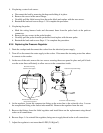
Teflon Washer
Brass Nut
29-inch (73.7 cm) leads
shown shortened for clarity.
Secure the high-limit
thermostat along the inside of
this leg with two metal wire ties.
Standoff


