


2. Aluminum lViring
A.
Connect length
of
copper building wire to
range terminal block.
IL
Splice
copper wires to aluminum wiring using
special connectors designed and
UT.L.
approved
for joining copper
to
aluminum, and follow the
connector
manufac~urer’s
recommended
procedure closely.
NOTE:
WTire
used, location and enclosure of
splices,
etc.,
must conform to good wiring
practice and
local
codes.
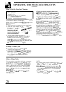
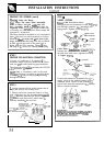
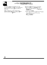
STEP
5
4-WIRE
SYSTEM
SPECIAL GROUNDING INSTRUCTIONS
WARNING:
I;rame grounded to neutral of appliance
through a link. If
usecl
in a MOBILE HOME or
if LOCAL
CODE3S
do
not permit grounding
through the neutral:
1) disconnect the link from neutral,
2)
use grounding terminal or lead to ground
unit in accordance with local codes, and
3)
connect nrutra] terminal 01
-
lead
to branch
circuit in usual manner.
(If
the appliance is to be connected
bv
means
of
a
cord
set, use
4-conductol:
cord
for this p
CO
NNECT”O
BL.OCK
\
GRO
LJND
4TH
G
LUG
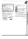
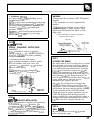
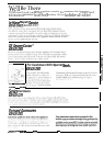
STEP b
ANTI-TIP
BRACKET INSTALLATION
AN
ANTI-TIP
bracket is supplied with instructions
for installation in
a
~~ariety
of
locations. The
instructions include a template,
a
parts
list
and a
list
f~f
tools necessary’ to
complete
the
installation.
Read
the
IMPORTANT
SAFETY
INSTIKJCTIONS
and
the instructions that fit your situation
before
b[ginning
installation,
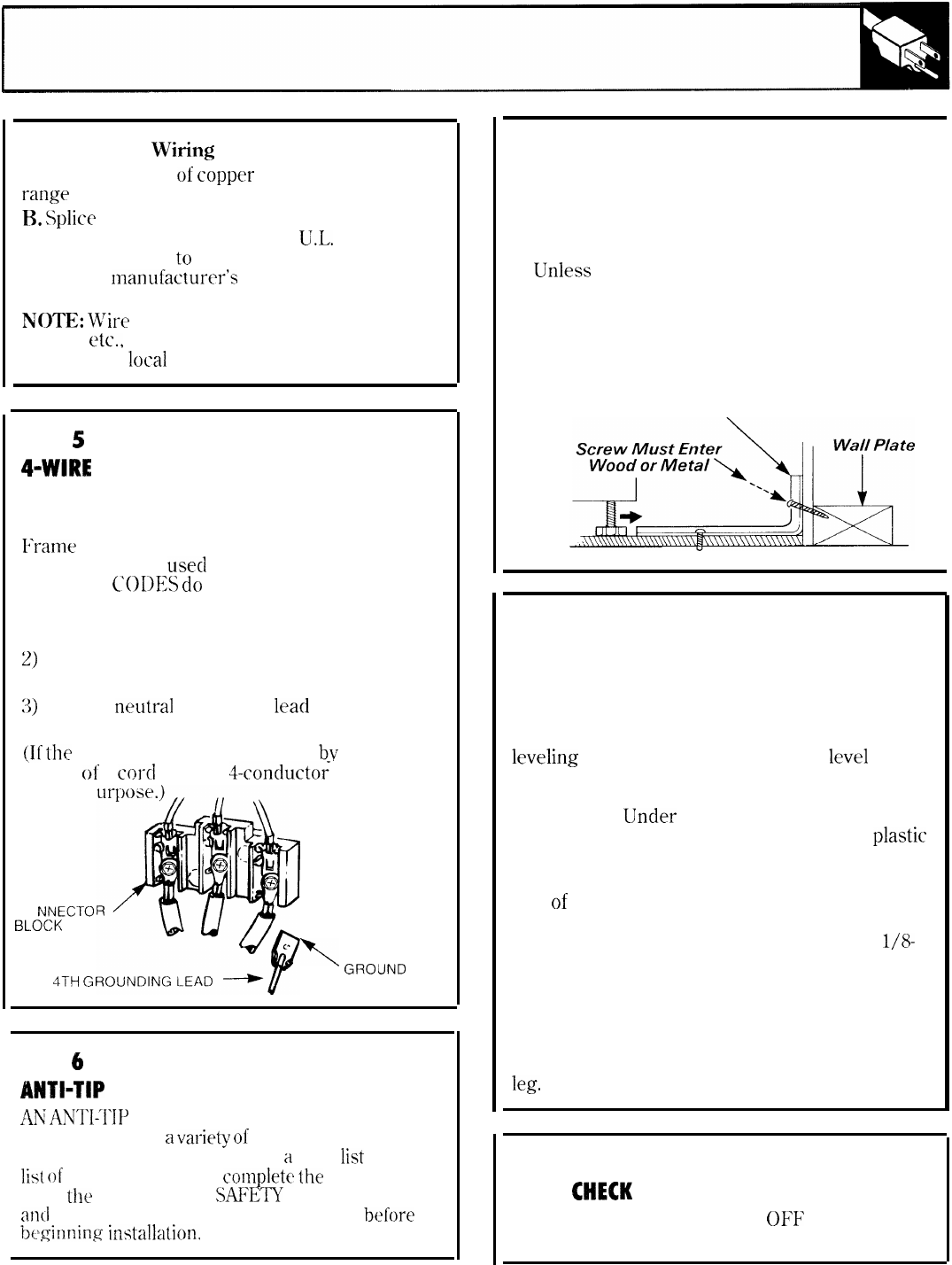
WARNING
1. Range must be secured by ANTI-TIP bracket
supplied.
2. See instructions to install (supplied with
bracket).
3.
Unless
properly installed, range could be
tipped by stepping or sitting on door. Injury
might result from spilled hot liquids or from
range itself.
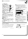
Typical installation of Anti-Tip bracket
Attachment to Wall
Bracket
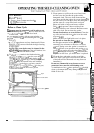
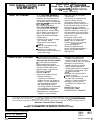
STEP 7
LEVELING THE RANGE
The range must be level. Leveling feet are located
at each corner of the base of the range. Remove
the storage drawer or kick panel (depending on
your model) and using channel locks, rotate the
leveling
feet in and out as required to
level
the
range. (For instructions on how to remove and
replace the storage drawer or the kick panel, see
the Cleaning [Jnder the Range section in Care
and Cleaning.) On some models, there are
plastic
covers which may be removed for easy
adjustment (just squeeze and pull).
One
of
the rear leveling feet will engage the
ANTI-TIP bracket (allow for some side to side
adjustment). Allow a minimum clearance of
l/8-
inch between the range and the leveling foot that
is to be installed into the ANTI-TIP bracket.
Check the range for proper installation into the
ANTI-TIP bracket (after the range has been
properly installed) by removing the kick panel or
storage drawer and inspecting the rear leveling
leg,
Make sure it fits securely into the slot.
STEP 8
FINAL
CHECK
Be sure all switches are in the OFF position
before leaving the range.
35