


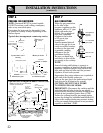
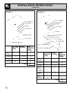
INSTALLATION INSTRUCTIONS
IMPORTANT SAFETY INSTRUCTIONS
The cooktop has been design certified by the
American Gas Association. As with any appliance
using gas and generating heat, there are certain
safety precautions you should follow. You’ll find
these precautions in your Use and Care Guide;
read it carefully.
• Be sure your cooktop is installed properly
by a qualified installer or service technician.
• The cooktop must be electrically grounded in
accordance with local codes, or in their absence,
with the National Electrical Code ANSI/NFPA
No. 70–Latest Edition.
• Installation of this cooktop must conform
with local codes, or in the absence of local
codes, with the National Fuel Gas Code. ANSI
Z223.1–Latest Edition.
• Disconnect electrical supply before servicing.
• Make sure the wall coverings around the
cooktop can withstand heat generated by the
cooktop up to 200°F.
• If cabinets are placed above the cooktop,
allow a minimum clearance of 30" between the
cooking surface and the bottom of protected
cabinets.
• Protect the underside of the cabinets above
the cooktop with not less than 1/4" insulating
flame retardant millboard covered with sheet
metal not less than 0.0122" thick.
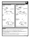
• Clearance between the cooking surface and
protected cabinets MUST NEVER BE LESS
THAN 30 INCHES. The vertical distance from
the plane of the cooking surface to the bottom of
adjacent overhead cabinets extending closer
than 2" to the plane of the cooktop sides must
not be less than 18". (See Dimensions and
Clearances illustration in this section.)
BEFORE YOU BEGIN
Read these instructions completely and
carefully.
IMPORTANT–OBSERVE ALL GOVERNING
CODES AND ORDINANCES.
Note to Installer: Be sure to leave these
instructions with the consumer.
TOOLS AND PARTS NEEDED
• Large flat blade screwdriver
• Saw
• Carpenter’s square
• Pipe wrench
• 7/16" open end wrench
• Gas line shut off valve
• Pipe joint sealant that resists action of LP gas
For flexible connection where local
codes permit:
• Flexible metal tubing (same 3/4" or 1/2" I.D.
as gas supply line)
• Flare union adapter for connection to supply line
(3/4" NPT x 3/4" I.D. or 1/2" NPT x 1/2" I.D.)
• Flare union adapter for connection to
regulator (1/2" NPT x 3/4" I.D. or 1/2" I.D.)
For rigid connection:
• Pipe fittings as required
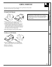
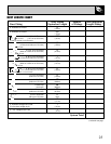
PARTS LIST
• Gas Cooktop base unit
• Literature pack
• 1 Surface burner assembly
• 2 Surface burner grates
• 1 Air filter
• 1 Air grill
• 1 Grease jar
• LP conversion kit (taped to the plenum)
18