


21
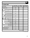
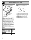
STEP 4
PROVIDE ADEQUATE GAS SUPPLY
This cooktop is designed to operate on natural
gas at 5" (12.7 cm) of water column pressure or
on LP gas at 10" (25.4 cm) of water column
pressure. It is shipped from the factory set for
natural gas. If you decide to use this cooktop with
LP gas, conversion adjustments must be made by
a service technician or other qualified person.
A pressure regulator is to be connected in series
with the manifold of the cooktop and must
remain in series with the supply line regardless
of whether natural or LP gas is being used.
For proper operation, the maximum inlet
pressure to the regulator must be no more
than 10" (25.4 cm) water column pressure
for natural gas, or 14" (35.5 cm) water
column pressure for LP gas. For checking
the regulator, the inlet pressure must be at least
1" (2.5 cm) greater than the regulator output
setting. If the regulator is set for 5" (12.7 cm)
of water column pressure, the inlet pressure
must be at least 6" (15.2 cm). If the regulator is
set for 10" (25.4 cm), the inlet pressure must be
at least 11" (27.9 cm).
For ease of installation, and if local codes permit,
the gas supply line into the cooktop should be
1/2" (12.7 mm) or 3/4" (19 mm) I.D. flexible metal
appliance connector 3 to 5 feet in length.
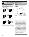
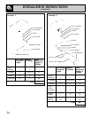
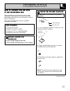
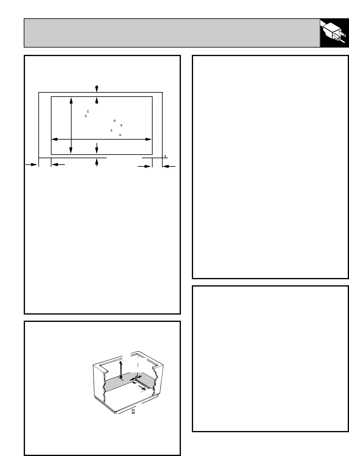
STEP 2
PREPARING THE COUNTERTOP
Cut out the opening as shown in the diagram.
Measure carefully when cutting the countertop,
making sure the sides of the opening are
parallel and the front and rear cuts are exactly
perpendicular to the sides.
The front of the opening must clear the front
support rail on the cabinet and the rear of the
opening must clear the rear support of the cabinet.
Chamfer all exposed edges of decorative laminate
to prevent damage from chipping.
Radius corners of cutout and file to insure
smooth edges and prevent corner cracking.
Rough edges, inside corners which have not been
rounded and forced fit can contribute to cracking
of the countertop laminate.
Countertop must be supported within 3" (7.6 cm)
of cutout.
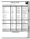
Not less than 1
7
⁄
8
"
4.8 cm
Not less than
15
⁄
16
" 2.4 cm
8
13
⁄
16
" min. cut-out
to wall (22.2 cm)
8
13
⁄
16
" min. cut-out
to wall (22.2 cm)
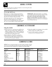
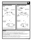
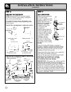
STEP 3
GAS AND ELECTRICAL LOCATION
The position of the
electrical supply
receptacle and the
gas supply pipe
entering the
cabinet should be
positioned as
shown in the
shaded areas
marked below.
The cooktop is
equipped with a 4' (111.7 cm) power cord, which
should reach any desired location on the cabinet
walls. The cooktop must be disconnected from the
power supply before any servicing is carried out.
19"
(48.2 cm)
14"
(35.5 cm)
(40.6 cm)
Power receptacle
Areas suitable for gas and electrical supply.
Countertop cut-out dimensions Back of Counter
Front of Counter
Gas inlet
STEP 5
PRESSURE TESTING
The maximum gas supply pressure for the
regulator supplied on this appliance is 14"
(35.5 cm) W.C. The test pressure for checking
this regulator must be at least 6" (15.2 cm) W.C.
for natural gas, and at least 11" (27.9 cm) W.C.
for LP. It is shipped from the factory set for
natural gas at 5" (12.7 cm) W.C.
This appliance and its individual shutoff valve
must be disconnected from the gas supply
piping system during any pressure testing of that
system at test pressures in excess of
1
⁄
2
PSIG.
This appliance must be isolated from the gas
supply piping system by closing its individual
manual shut off valve during any pressure
testing of the gas supply piping system at test
pressures equal to or less than
1
⁄
2
PSIG.
16"
(continued next page)
20
15
⁄
16
1
⁄
16
"
53.2 .16 cm
28
15
⁄
16
1
⁄
16
" (JGP389)
73.3 cm .16 cm
17
1
⁄
8
1
⁄
16
" (JGP18)
43.5 cm .2 cm