


INSTALLATION INSTRUCTIONS
(continued)
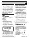
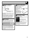
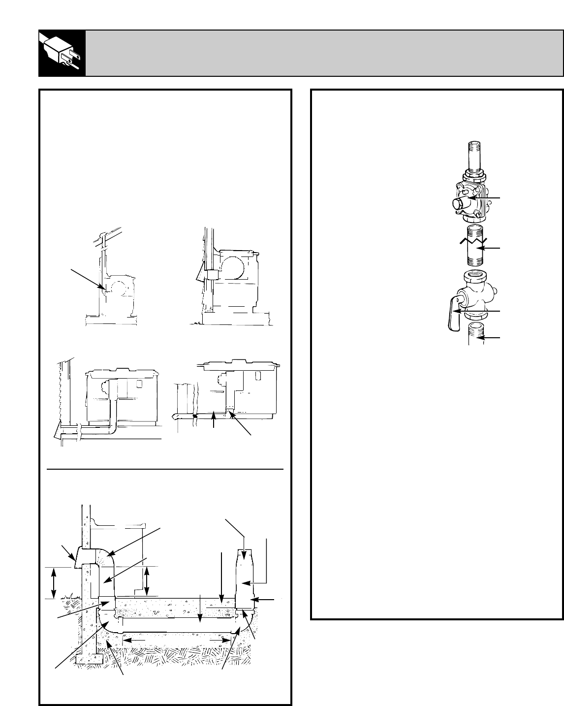
STEP 7
GAS CONNECTION
Make the gas connection
to the inlet of the
pressure regulator on this
appliance with a 1/2" pipe
nipple with male pipe
thread. Use an approved
pipe joint compound
resistant to the action
of LP gas at pipe
connections.
Install a manual shut-off
valve in the gas line in an
easily accessible location,
as close to the pipe stub
as possible, making
allowances for the
ventilation ducting.
Be sure you know how
and where to shut off the
gas supply to the cooktop.
NOTE:
Instead of using solid piping to connect to
pressure regulator, an approved flexible metal
appliance connector may be used between the
pipe stub and shut off valve and the pressure
regulator, if local codes permit.
Appropriate flare union adapters are required at
each end of the flexible connector.
Turn on the gas; check for leaks using a liquid
leak detector at all joints in the system.
CAUTION: DO NOT USE A FLAME
TO CHECK FOR GAS LEAKS.
IMPORTANT—Disconnect the cooktop and the
individual shut off valve from the gas supply
piping system during any pressure testing of that
system at test pressures greater than
1
⁄
2
PSIG.
Isolate the cooktop from the gas supply piping
system by closing the individual manual shut off
valve to the cooktop during any pressure testing
of the gas supply piping system at test pressures
equal to or less than
1
⁄
2
PSIG.
1/2" Threaded
pipe nipple
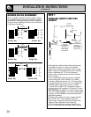
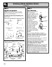
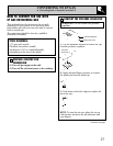
STEP 6
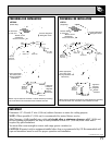
PREPARE FOR DUCTWORK
NOTE: Ductwork MUST be vented outside.
DO NOT vent into a wall, ceiling, crawlspace,
attic or any concealed space.
Determine the best route for ductwork; it can
be routed in a variety of ways depending on the
kitchen layout.
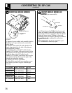
Typical duct arrangement countertop series.
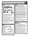
Optional duct arrangement under concrete slab.
Pipe stub
Shut-off valve
Gas appliance
pressure
regulator
Inside wall
cabinet
Up inside wall to roof or
overhang.
Directly to outside.
Between floor joists. Thru cabinet toe space.
Peninsula or island
Peninsula
Outside wall
cabinet
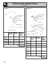
3
1
⁄
4
"X10"
(8.2 cm X 25.4 cm)
Transition elbow
Transition
elbow
3
1
⁄
4
"X10"
(8.2 cm X 25.4 cm)
22
NOTE: PVC sewer pipe type PSM 12454-B
Schedule 40 ASTM D1785.
Wall cap
6″ (15 cm)
Dia. 90°
Metal Elbow
6″ (15 cm) Dia.
Metal Duct
16″
(40.6 cm)
Max.
Concrete
slab
6″ (15 cm)
Dia. PVC
Sewer Pipe
12″
(30 cm)
Min.
6″
(15 cm)
Dia. PVC
coupling
6″
(15 cm)
Dia.
PVC
coupling
6″ (15 cm)
Dia. Metal
duct
5″ to 6″
(12.7 cm to 15 cm)
Metal transition
6″ (15 cm)
Dia. PVC
Sewer
pipe
6″ (15 cm) Dia.
PVC Sewer pipe
elbow
6″ (15 cm) Dia.
PVC Sewer pipe
elbow
Pack tightly with gravel
or sand completely
around pipe.
30′ (9.1 m)-0″ Max