


– 25 –
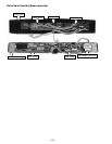
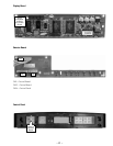
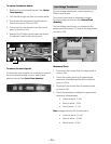
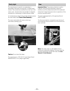
Control Panel Assembly
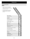
The control panel assembly consists of an outer
control panel and an inner control panel bracket.
The outer control panel contains the control, display,
and selector circuit boards. The power and relay
circuit boards, and the low voltage transformer are
attached to the control panel bracket. Removing the
control panel allows access to the oven lamp.
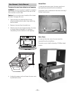
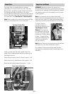
The control panel is held in place with 7 Phillips-
head screws and 4 tabs. Two of the screws are
recessed from the top of the outer cover. Access
holes are provided. A magnetic screwdriver is
necessary to capture these screws.
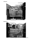
To remove the control panel assembly:
Place the oven in a partially removed position.
(See Oven Removal / Partial Removal.)
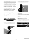
Remove the 3 Phillips-head screws from the top
front of the outer cover.
1.
2.
(Continued Next Page)
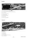
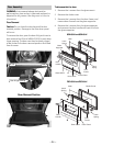
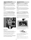
3. Remove the 2 recessed Phillips-head screws
that attach the control panel assembly to the
top of the frame.
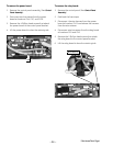
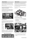
5. Open the oven door.
Grasp the bottom of the control panel assembly
and lift to release the 4 tabs that hold the
bottom of the control panel assembly to the
oven frame.
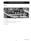
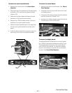
Disconnect wire harnesses from the power
board at locations CN5, CN6, and CN8.
Disconnect wire harnesses from the relay board
at locations RY2, RY7, RY8, RY9, RY11, and CN2.
6.
7.
8.
4. Remove the 2 Phillips-head screws that attach
the control panel assembly to the side of the
frame.