


– 39 –
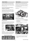
5. Test Circuit Operation.
a. Connect temporary jumper leads across
relay contacts, primary interlock and door
sensing switches to simulate shorted switch
contacts. Locate convenient connections in
circuit to be certain COM and NO terminals
are used.
b. Connect ohmmeter (Rx1) across the line
terminals of the appliance cord. Continuity
must show the following:
• Door Closed : Some Ω
• Door Open : .3 Ω
c. Remove 20 amp fuse. Circuit must open
(infi nity
Ω). If not, check wiring of monitor
and interlock circuits.
WARNING: After test, remove temporary jumper
leads from interlock and relay.
WARNING: Primary interlock, door sensing switch,
monitor switch, and relay board must be replaced
when the 20 amp fuse is blown due to operation of
monitor switch.
Note: Perform microwave leakage test when
replacing or adjusting interlock switches or latch
board.
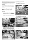
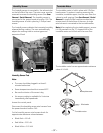
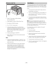
How to Adjust the Interlocks:
The latch board is adjustable for proper door closure
and switch operation.
Disconnect power and partially remove the
oven from it’s installation. (See Oven Removal /
Partial Removal.)
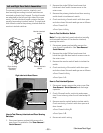
Note: Each latch board is held in place and adjusted
with 2 Phillips-head screws. The screws are recessed
from the top of the outer cover. Access holes are
provided.
2. Loosen the 2 Phillips-head screws that attach
the latch board to the oven chassis.
3. Adjust each latch-board for proper door closure
and switch operation, retighten screws.
Note: Perform microwave leakage test when
replacing or adjusting interlock switches or latch
boards.
1.
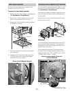
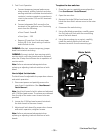
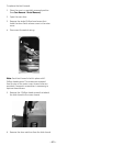
To replace the door switches:
Place the oven in a partially removed position.
(See
Oven Removal / Partial Removal.)
Open the oven door.
Remove the single Phillips-head screw that
holds the door switch access cover to the outer
cover.
Disconnect the switch wiring.
Using a fl at blade screwdriver, carefully press
the lock tab until fl ush with the surrounding
area of the latch board.
Using the mounting pin as a pivot, carefully
rotate the switch past the lock tab and
Remove the switch from the mounting pin.
1.
2.
3.
4.
5.
6.
Lock Tab
Pivot Pin
Rotate Switch
(Continued Next Page)