


– 30 –
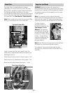
Capacitor and Diode
WARNING: Always be certain the capacitor is
discharged before servicing. Mechanically discharge
by placing an insulated handle screwdriver between
the diode connection of the capacitor and the oven
chassis ground.
Note: The capacitor has an internal discharge
resistor that automatically discharges the capacitor
when the oven turns OFF. Under normal operation,
capacitor should fully discharge within 30 seconds.
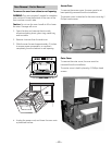
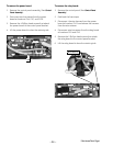
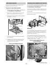
The oven must be
partially removed to
access the capacitor. (See
Oven Removal / Partial
Removal.) The capacitor
is located behind the top
access cover and is held
in place by 2 Phillips-head
screws. A single Phillips-
head screw attaches the
capacitor and diode to
the oven chassis.
Note: When disconnecting the wires and diode from
the capacitor, note wire and diode locations.
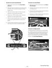
The capacitor wires have locking tabs. Remove
the capacitor, capacitor bracket, and diode as one
assembly.
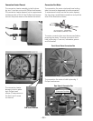
Diode
Screw
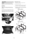
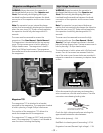
Noise Filter
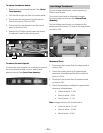
The noise fi lter is located behind the blower
assembly on the right side of the oven. The noise
fi lter is held in place by a single Phillips-head screw.
The fi lter ground wire is attached to the oven
chassis near the noise fi lter by a single Phillips-head
screw. The outer cover must be removed to access
the noise fi lter. (See
Oven Removal / Partial Removal.)
Note: When installing the noise fi lter, ensure all fi lter
wiring is connected to the correct terminals.
Input
Wire
Harness
Output-N
Output-L
Ground Wire Screw
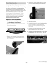
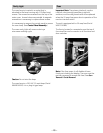
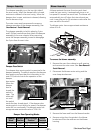
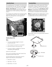
Check to make sure the fuse is good. Check the
noise fi lter for approximate resistance value at the
following locations:
White (neutral input) to white (neutral output) - 0 Ω
Black (line input) to black/brown (line output) - 0 Ω
White (neutral input) to black (line input) - 23 Ω
Top View of Noise Filter
Noise Filter
Screw
Front View of Noise Filter