


10 4034-102 Rev F 02/04
HRV200PLUS INSTALLATION INSTRUCTIONS
1. Location
The HRV200PLUS must be located in a heated space where it will be possible to conveniently service the ventilator. Typically the
HRV200PLUS would be located in the mechanical room or an area close to the outside wall where the weather hoods will be
mounted. If a basement area is not convenient, a utility or laundry room may be used.
Attic installations are not normally recommended due to:
a. The complexity of work to install.
b. Freezing conditions in the attic.
c. Difficulty of access for service and cleaning.
Sufficient clearance at the front of the access door is required for servicing the air filters and core. A minimum of 25 (635mm)
clearance is recommended so the door can be opened. Four PVC reinforced polyester hanging straps are provided for hanging the
HRV200PLUS from the basement floor joists.
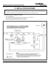
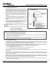
2. Mounting
The hanging straps should be attached to the ventilator at the top end corners (mounting screws are already located on the
ventilator case). Securely fasten the other end of the straps to the floor joists with wide head nails (not supplied), making sure the
ventilator is level. The straps are designed to reduce the chance of noise, resonance or harmonics; therefore using the full length
of the strap between the HRV200PLUS and the floor joists is recommended.
F. INSTALLING THE VENTILATOR
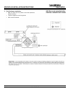
WARNING!
In order to prevent electric shock when cleaning or servicing the HRV200PLUS, it is extremely important to confirm the
polarity of the power line that is switched by the safety (disconnect) switch. The hot line (black) is the proper line to be
switched. To confirm the proper polarity, use a voltmeter or test lamp to ensure there is no power after the switch when the
door is open. Check between that point and ground (on the cabinet). This must be done as dwellings are occasionally
wired improperly. Always make sure that the HRV200PLUS is properly grounded.
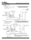
3. Electrical
The HRV200PLUS should be plugged into a standard designated (120VAC) electrical outlet with ground. The HRV200PLUS is
equipped with a 3 foot electrical cord so it should be located within 3 feet from electrical service. It is not recommended that an
extension cord be used for this appliance. If further wiring is required, then a licensed electrician should make all electrical connections.
It is recommended that a separate 15 amp/120 volt circuit be used.
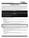
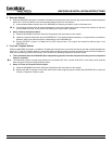
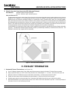
4. Installing the Drain Line and P-Trap
When defrosting, the HRV200PLUS may produce some condensation. This water should flow into a nearby drain or be taken away
by a condensate pump. The ventilator and all condensate lines must be installed in a space where the temperature is maintained
above the freezing point.
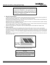
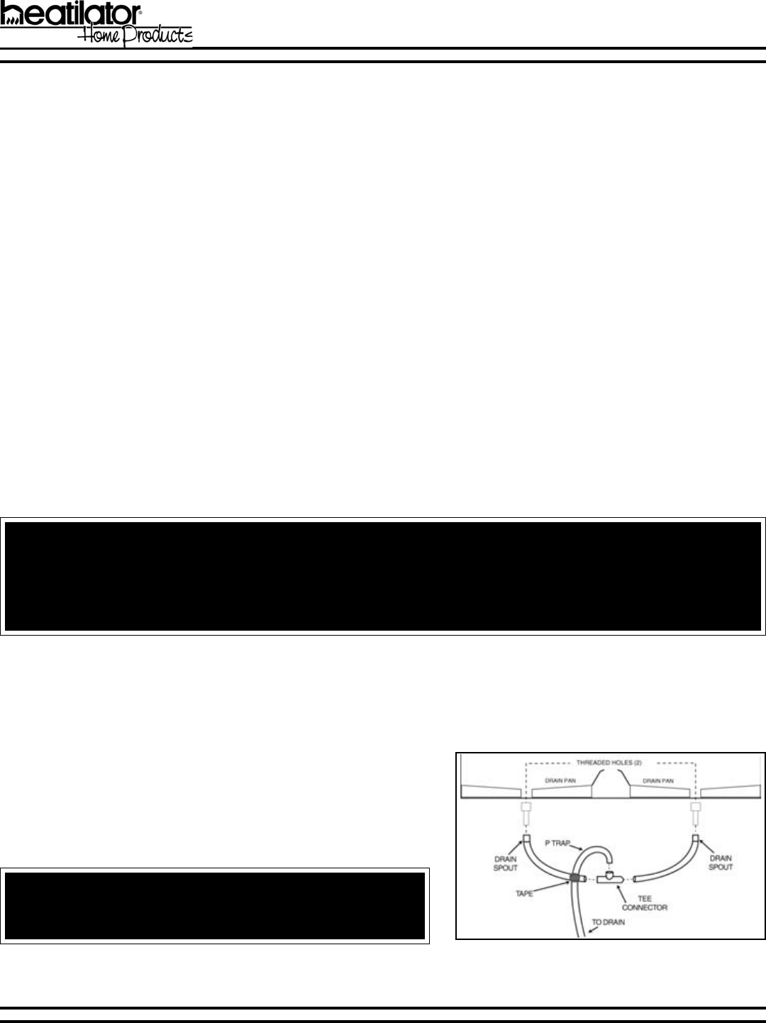
Figure 1
WARNING!
Improperly installed water drain lines could result in property dam-
age.
Construct a P-Trap using the plastic tee connector. Cut two lengths of
hose and connect each piece to an end of the T fitting, then connect
the other ends to the two drain spouts. Allow the T fitting to point
upwards. Connect to the drain line. Tape or fasten the base to avoid
any kinks. This creates a trap which will hold some condensate and
prevent odors from being drawn up the hose and into the fresh air supply
of the HRV200PLUS. See Figure 1.