


16 4034-102 Rev F 02/04
HRV200PLUS INSTALLATION INSTRUCTIONS
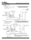
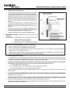
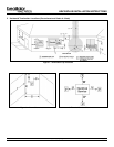
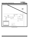
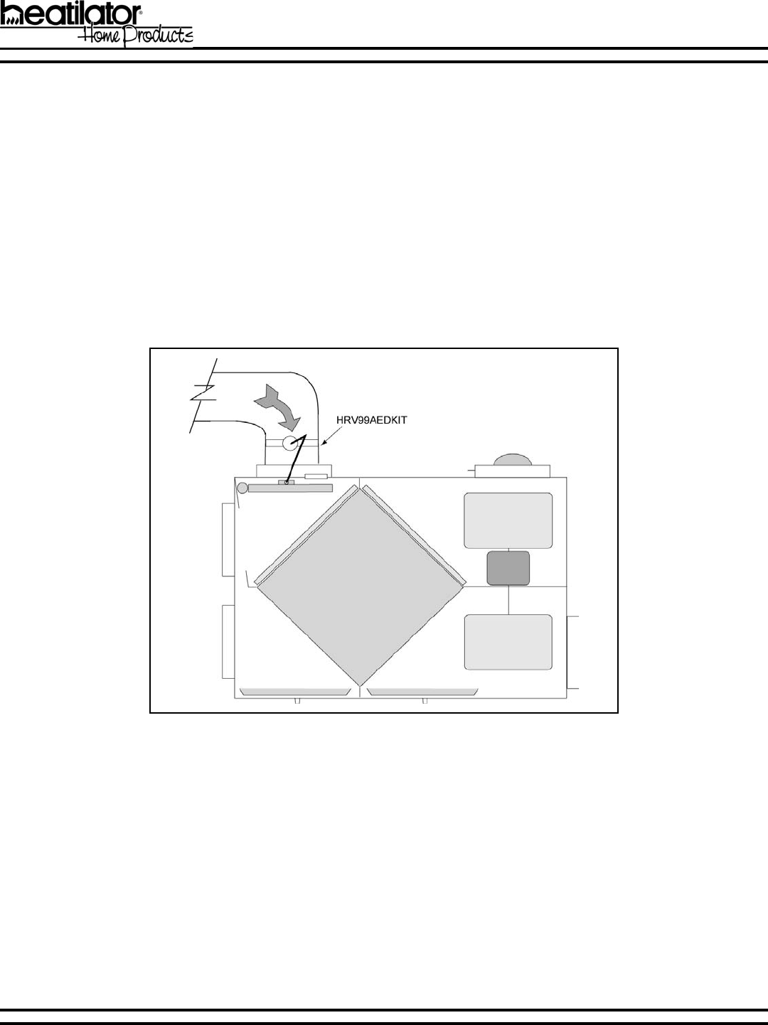
5. Stale Air from the Living Area to the HRV (Alternate Exhaust)
Duct Materials: Alternate Exhaust Damper Assembly
Air Duct - flexible or rigid, insulation optional
Alternate Exhaust Port
The alternate exhaust port is used to draw air from the points in the house where the worst air quality problems occur, when the
fireplace is not in operation. It is recommended that return air ducts are installed in the bathroom, kitchen and laundry room.
Additional return air ducts from strategic locations (i.e. greenhouse, atrium, swimming pool, sauna, etc.) may be installed.
Also, the furnace return duct may be used for exhaust. In this method, the exhaust air is not ducted back to the HRV200PLUS
with dedicated lines from bathrooms, kitchens, etc. Instead, the exhaust air is drawn out of the cold air return of the forced air
furnace. This method has become popular and provides good ventilation when installed in accordance with the instructions.
The furnace blower must be running when the ventilator is operating for this system to be effective.
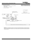
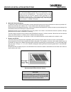
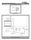
The HRV200PLUS comes factory wired ready to allow installation and operation of the Alternate Exhaust Damper Assembly
(Figure 4). The Alternate Exhaust Damper Assembly should be professionally installed by a trained service technician. The
installation instructions are supplied with the assembly.
Figure 4 - Alternate Exhaust Damper
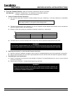
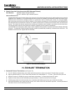
H. EXHAUST TERMINATION
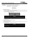
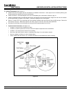
1. Horizontal Exhaust Terminations (see Figures 5-9)
a. Cut a 9 (229mm) diameter hole in the outside wall of the structure to allow the CoolVent Flexible Pipe to protrude.
b. Apply a generous bead (½) of RTV around the perimeter of the collar/adapter 2 - 3 (51mm - 76mm) from the open end.
c. Slide the CoolVent Flexible Pipe over the termination collar about 1 (25.4mm) beyond the RTV bead.
d. Tighten the hose clamp around the flexible pipe approximately 1 (25.4mm) from the end of the pipe.
e. Carefully apply pressure to the termination cap, compressing the flexible pipe until the cap is flush with the siding.
f. Secure the termination cap in place with four screws, one in each corner of the termination cap base. Caulk the perimeter of
the base to form an air and moisture proof seal.