


20 4034-102 Rev F 02/04
HRV200PLUS INSTALLATION INSTRUCTIONS
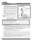
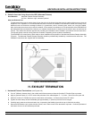
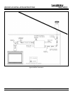
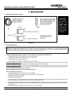
f. Typical Vertical Termination (see Figure 10)
At least 10 (3m) from the ventilation air intake.
At least 18 (457mm) above the roof line or above the depth of expected snow accumulation.
At least 3 (1m) away from the corner of the building.
Not near a gas meter, electric meter or a walkway where fog or ice could create a hazard.
Not into a garage, workshop or other enclosed space.
When installing the termination cap, its outside perimeter must be sealed with exterior caulking.
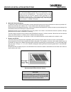
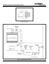
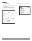
3. Vertical Termination (see Figure 11)
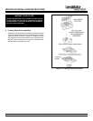
a. Install the B-Vent roof support per the manufacturers installation instructions. Insure proper use of necessary flashing and
firestop spacers as required by the vent manufacturer.
b. Install a CoolVent Universal Adapter to the end of the flexible pipe as described in Step 4b, page 15.
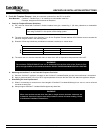
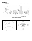
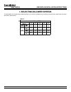
c. Install an adequate length of rigid B-Vent pipe into the roof support to provide the minimum height from the roof to the bottom
of the cap as shown in Figure 12 and Table 1. Secure the rigid pipe in the roof support.
d. Place a ½ bead of RTV in the receiving end of the appliance adapter and insert the end of the rigid B-Vent pipe. Secure the
hose clamp to the pipe. Reference Figure 5 and inset in Figure 10 for RTV and hose clamp placement.
e. Use aluminum duct tape to seal all seams of the rigid B-Vent exposed below the roof line.
Figure 10