


02/04 4034-102 Rev F 11
HRV200PLUS INSTALLATION INSTRUCTIONS
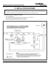
G. VENT AND DUCT INSTALLATION
The HRV200PLUS (HRV) not only serves as the fresh air ventilator for the home, but is also the power venting device for the Fresh Air
Fireplace (FAF). The conduits from the FAF to the HRV and from the HRV to the exhaust termination remove both stale air from the
home and the products of combustion from the FAF. Thus the exhaust air conduit acts as the chimney for your fireplace!
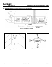
The HRV200PLUS requires four standard and one optional vent/duct connections:
Standard
1. Fresh Air Supply - Fresh air from the Fresh Air Inlet to the HRV.
2. Warmside Air Supply - Heated fresh air from the HRV into the living area.
3. Fresh Air Fireplace Exhaust - Stale air/combustion products from the FAF to the HRV.
4. HRV Exhaust - Stale air/combustion products from the HRV to the Flue Exhaust.
Optional - Alternate Exhaust Damper Assembly
Alternate Exhaust - Stale air from the living area to the HRV.
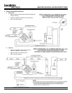
1. Fresh Air From the Outdoor Intake to the HRV (Fresh Air Supply)
Duct Materials: Fresh Air Inlet - 6 Outside Weatherhood (Part #HRV99189)
Insulated Air Duct - rigid or flexible
CoolVent Flexible Pipe may be used.
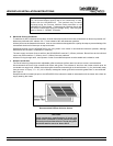
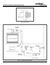
a. Locate the Fresh Air Inlet
See Figure 7 for more detailed instructions.
Must take air directly from outdoors.
Should be located upstream (if there are prevailing winds) from the exhaust outlet.
At least 3 (.9m) below when within 10 (3m) of the exhaust weatherhood, dryer vents or furnace exhaust
(medium or high efficiency furnaces).
A minimum of at least 10 (3m) from driveways, oil fill pipes, gas meters, garbage containers or any other
know sources of contamination.
At least 18 (457mm) above the ground or above the depth of expected snow accumulation.
At least 3 (1m) from the corner of the building.
Do not locate in a garage, attic or crawl space, adjacent dwelling units or other indoor spaces.
Cap with the included plastic weatherhood.
Must be clear of future obstructions such as plants, snow, etc.
Must be readily accessible for clearing of debris and obstructions.
Note: Each of these connections has specific requirements for safe
system operation, comfort and optimum efficiency. Always try to mini-
mize duct run length and follow the manufacturer’s installation in-
structions. Always follow specific code requirements.
WARNING! - CONNECTING APPLIANCES TO THE HRV200PLUS
Do not connect any of the following appliances to the HRV200PLUS because lint, dust and/or grease will collect in the HRV,
damaging the ventilator:
clothes dryer gas furnace gas water heater
range top B-vented gas fireplace direct vent gas fireplace
stove top fan solid fuel fireplace or heater central vacuum system
Connecting any of these appliances to the HRV200PLUS will void the warranty.