


26 4034-102 Rev F 02/04
HRV200PLUS INSTALLATION INSTRUCTIONS
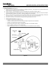
3. Pitot Tube Balancing Procedure (see Figure 16)
The following is a method of field balancing an HRV200PLUS using a pitot tube, advantageous in situations when flow
stations are not installed in the duct work. The procedure should be performed with the HRV200PLUS on high speed.
The first step is to operate all mechanical systems that have an influence on the ventilation system (i.e. the HRV itself and the
forced air furnace or air handler if applicable) on high speed. This will provide the maximum pressure that the HRV200PLUS will
need to overcome and allow for a more accurate balance of the ventilator.
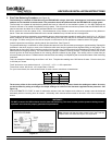
Drill a small hole in the duct (about 3/16), 3 feet downstream of any elbows or bends, and one foot upstream of any elbows or
bends. These are recommended distances but the actual installation may limit the amount of straight duct.
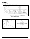
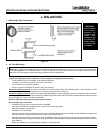
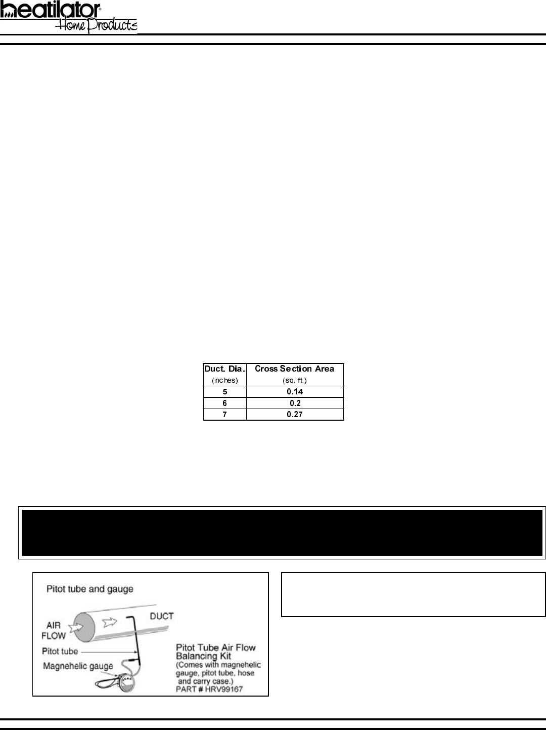
The pitot tube should be connected to a magnehelic gauge or other manometer capable of reading from 0 to 0.25 in. (0 - 62 PA) of
water, preferably to three digits of resolution. The tube coming out of the top of the pitot is connected to the high pressure side of
the gauge. The tube coming out of the side of the pitot is connected to the low pressure or reference side of the gauge.
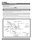
Insert the pitot tube into the duct; pointing the tip into the air flow. See Figure 15.
For general balancing it is sufficient to move the pitot tube around in the duct and take an average or typical reading. Repeat this
procedure in the other (supply or return) duct. Determine which duct has the highest air flow (highest reading on the gauge). Then
damper that air flow back to match the lower reading from the other duct. The flows should now be balanced. Actual air flow can be
determined from the gauge reading. The value read on the gauge is called the velocity pressure. The pitot tube comes with a chart
that will give the air flow velocity based on the velocity pressure indicated by the gauge. This velocity will be in either feet per
minute or meters per second. To determine the actual air flow, the velocity is multiplied by the cross sectional area of the duct being
measured.
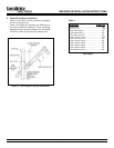
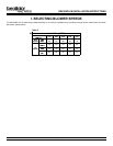
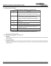
This is an example of determining the air flow in a 6 duct. The pitot tube reading was 0.025 inches of water. From the chart, this
is 640 feet per minute.
The 6 duct has a cross sectional area of = [3.14 x (6 ÷ 12)² ÷ 4 = 0.2 square feet
The air flow is then: 640 ft./min. x 0.2 square feet = 128 cfm
For your convenience, the cross sectional area of some common round duct is listed below:
Figure 15
The accuracy of the air flow reading will be affected by how close to any elbows or bends the readings are taken. Accuracy
can be increased by taking an average of multiple readings as outlined in the literature supplied with the pitot tube. See
Figure 16.
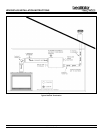
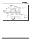
If the ALTERNATE 5TH PORT is used for alternative exhaust, both the fireplace and exhaust air streams must be balanced
individually with the incoming fresh air stream. Individually, each exhaust stream needs to be within 10% of the incoming air
stream.
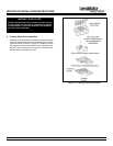
Note: Always seal the pitot tube access hole in the Fresh Air
Fireplace duct with aluminum tape or the equivalent.
WARNING!
DO NOT penetrate the HRV exhaust duct for pitot tube balancing. This duct is under positive pressure during normal
operation and cannot be properly patched once penetrated!