


02/04 4034-102 Rev F 29
HRV200PLUS INSTALLATION INSTRUCTIONS
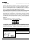
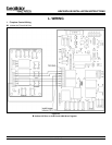
K. OPERATING MODES
The operating mode of the HRV200PLUS is determined by the status of the control inputs:
1. Fireplace Control Input Group Connector P9
LO, HI, 12V, COM, C1, C2, R2, R1
2. Thermostat Control Inputs Connector P6
TCOM, TSTAT
3. Ventilation Control Input Group Connector P1
R, B, O, W, G
4. Furnace Interface Control Group Connector P3
FNC, FCOM, FNO
The Fireplace Control Input Group represents the home owners desire for fireplace operation and are considered first priority by the
HRV200PLUS controller. These inputs include signals from the fireplace dashboard controls, fireplace remote controls and dedicated
hearth room thermostats. Inputs to activate the fireplace from this control group are processed with no regard to the other two input
groups.
The Thermostat Control Inputs are used to couple the HRV200PLUS to the primary heating system to provide comfort heating when the
temperature at the main thermostat falls below the set point. The Thermostat Control will not shut off the Fresh Air Fireplace if there is
an input from the Fireplace Control Input Group.
The Ventilation Control Input Group receives signals from the ventilation controls installed with the system to maintain desired fresh air
ventilation rates in the building envelope. Since the Fresh Air Fireplace operation requires continuous high speed ventilation, the
Ventilation Control Inputs are ignored unless the Fresh Air Fireplace in not in use.
The Furnace Interface Control Group consists of a single pole, double throw set of contacts to provide an interface with the furnace
control board and the main thermostat to enable furnace blower operation to distribute fresh air through the existing duct work.
1. Fireplace Operating Modes Connector P9
a. OFF Mode
The HRV is idle until an input is sensed. This is the normal standby state when the HRV Plus is powered but not receiving any
command inputs.
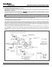
b. Fireplace High Fire Mode
All fireplace demands for fireplace operation from the hearth room result in a 12VDC signal sent to the HRV controller HI
input terminal on the P9 connector strip. This includes the ON/OFF switch on the fireplace, demands from the fireplace remote
control and heating calls from a dedicated fireplace thermostat.
Fireplace High Fire Mode is activated when 12VDC is sensed at the HI input terminal. The HRV/Fresh Air Fireplace system
executes pre-purge and ignition processes as follow:
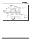
c. Caliber NXT Plus/6100 PLUS
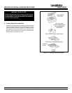
1) Initiation
a) Blower motor on HIGH for system pre-purge.
b) C2 terminal is energized 12VDC activating the electric ember lights on the Fresh Air Fireplace.
c) Fifteen-second pre-purge timer activates while the HRV closes the alternate exhaust damper.
d) C1 terminal is energized 12VDC to override the pressure switch in the Fresh Air Fireplace.
e) R1 is energized 12VDC activating the IPI ignition circuit to initiate the fireplace ignition process. In the HRV, the R2
terminal must be jumpered to 12V to supply power to R1 at the Fresh Air Fireplace.
f) The thirty-second draft-proving delay timer activates.
g) The Fresh Air Fireplace lights.
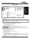
h) The thirty-second draft-proving delay timer expires, C1 terminal is de-energized and the Fresh Air Fireplace pressure
switch is monitored for sufficient flow at the flue collar for proper operation. IF SUFFICIENT FLOW IS NOT SENSED
AT THE FLUE COLLAR OF THE FRESH AIR FIREPLACE AFTER THIRTY SECONDS OF OPERATION, THE FRESH
AIR FIREPLACE FLAMES WILL EXTINGUISH LEAVING THE ELECTRIC EMBERS ILLUMINATED ONLY. THE
FRESH AIR FIREPLACE WILL NOT SUSTAIN NORMAL OPERATION UNTIL THE LACK OF FLOW IS CORRECTED!