


02/04 4034-102 Rev F 15
HRV200PLUS INSTALLATION INSTRUCTIONS
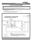
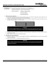
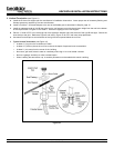
4. HRV Exhaust - Stale air/combustion products from the HRV to the Flue Exhaust
Duct Materials: CoolVent Flexible Pipe - Zero Clearance to Combustible Materials
Horizontal Terminations: CoolVent Termination Cap
Vertical Terminations: CoolVent Universal Adapter
B-Vent Roof Support
B-Vent Pipe Sections
B-Vent Termination Cap
a. HRV Plus Exhaust Guidelines
1) HRV must be vented with CoolVent flexible insulated vent pipe. The CoolVent flexible pipe can be installed with zero
clearance to combustible materials when used as the HRV Exhaust.
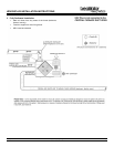
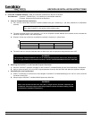
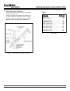
2) The total combined length of the CoolVent vent run for the Fresh Air Fireplace Exhaust the HRV Exhaust must not
exceed the maximum lengths in the following table:
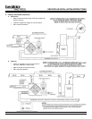
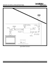
3) Direction of flow may include any combination horizontal, vertical up or vertical down, but must not form a trap for
condensation to collect.
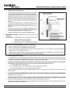
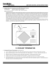
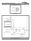
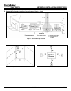
4) Refer to Figures 7-9 for horizontal termination locations.
b. Assembling the Vent Pipe Sections
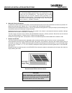
1) When it is necessary to connect two or more lengths of CoolVent insulated flexible pipe in a vent run, use a universal
connector at each joint.
2) Always support CoolVent insulated flexible pipe every three feet.
WARNING!
The maximum TOTAL EXHAUST vent run is measured from the flue collar of the Fresh Air Fire-
place, through the HRV, to the outside termination. DO NOT EXCEED MAXIMUM VENTING LENGTHS!
WARNING!
When vent pipe sections exceed three feet (.9m) in length, structural support must be provided to
reduce off-center loading and insure minimum clearances are maintained. Follow manufacturers
installation instructions.
Æ