


13
VIII. GAS SUPPLY, CONDENSATE DRAIN AND
VIII. PIPING
A. GAS CONNECTION
IMPORTANT: Connect this unit only to gas supplied by a commercial utility.
1. Install gas piping in accordance with local codes and regulations of the local utility
company. In the absence of local codes, the installation must conform to the specifi-
cations of the National Fuel Gas Code, ANSI Z223.1 - latest edition.
NOTE: The use of flexible gas connectors is not permitted. If local codes allow the
use of a corrugated stainless steel flexible gas appliance connector, always use a
new listed connector. Do not use a connector which has previously serviced another
gas appliance.
NOTE: The Commonwealth of Massachusetts requires the gas shut-off valve to be a
T-handle gas cock.
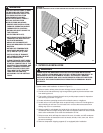
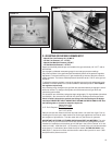
2. Connect the gas line to the gas pipe inlet opening provided into the 1/2؆ inlet valve.
See Figure 5 or 8 for typical piping.
3. Size the gas line to the furnace adequate enough to prevent undue pressure drop
and never less than 1/2؆ nominal pipe size.
4. Install a drip leg or sediment trap in the gas supply line as close to the unit as possi-
ble.
5. Install an outside ground joint union to connect the gas supply to the control assem-
bly at the burner tray.
6. Gas valves have been factory installed. Install a manual gas valve where local codes
specify a shut-off valve outside the unit casing. (See Figure 13.)
7. Make sure piping is tight. A pipe compound resistant to the action of liquefied
petroleum gases must be used at all threaded pipe connections.
8. IMPORTANT: any additions, changes or conversions required for the furnace to sat-
isfactorily meet the application should be made by a qualified installer, service
agency or the gas supplier, using factory-specified or approved parts. In the com-
monwealth of Massachusetts, installation must be performed by a licensed plumber
or gas fitter for appropriate fuel.
IMPORTANT: Disconnect the furnace and its individual shutoff valve from the gas sup-
ply piping during any pressure testing of that system at test pressures in excess of 1/2
pound per square inch gauge or isolate the system from the gas supply piping system
by closing its individual manual shutoff valve during any pressure testing of this gas sup-
ply system at pressures equal to or less than 1/2 PSIG.
TO CHECK FOR GAS LEAKS, USE A SOAP AND WATER SOLUTION OR OTHER
APPROVED METHOD. DO NOT USE AN OPEN FLAME.
IMPORTANT: Check the rating plate to make certain the appliance is equipped to burn
the type of gas supplied. Care should be taken after installation of this equipment that
the gas control valve not be subjected to high gas supply line pressure.
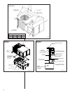
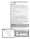
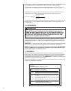
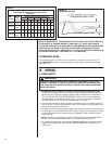
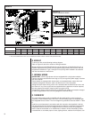
FIGURE 13
SUGGESTED GAS PIPING
FROM GAS
METER
*
Factory supplied grommet must be utilized.
MANUAL GAS
SHUT-OFF
VALVE
UNIT GAS SUPPLY
CONNECTION
*
ROOF OR GROUND LEVEL INSTALLATION
!
WARNING
CHECK FOR LEAKS. THE USE OF AN OPEN FLAME CAN RESULT IN FIRE,
EXPLOSION, PROPERTY DAMAGE, PERSONAL INJURY OR DEATH.
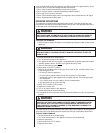
Nominal
Iron Pipe
Size,
Inches
Equivalent Length of Pipe, Feet
10 20 30 40 50 60 70 80
1
⁄2 132 92 73 63 56 50 46 43
3
⁄4 278 190 152 130 115 105 96 90
1 520 350 285 245 215 195 180 170
1
1
⁄4 1,050 730 590 500 440 400 370 350
1
1
⁄2 1,600 1,100 890 760 670 610 560 530
TABLE 1
NATURAL GAS PIPE CAPACITY TABLE (CU. FT./HR.)