


19
rays, lamps, televisions, radios or air streams from registers. Refer to instructions
packed with the thermostat for “heater” selection or adjustment.
X. FURNACE SECTION CONTROLS AND
IGNITION SYSTEM
NORMAL FURNACE OPERATING SEQUENCE
This unit is equipped with an integrated direct spark ignition control.
1. The thermostat calls for heat.
2. The control board will run a self check to verify that the limit control and manual reset
overtemperature control are closed and that the pressure switch is open.
3. Upon closure of the pressure switch, the control board energizes the induced draft
blower for a 15 second prepurge.
4. After the 15 second prepurge, the gas valve opens and the spark is initiated for 7 sec-
ond trial for ignition.
5. Burners ignite and flame sensor proves all burners have lit.
6. The circulating air blower is energized after 30 seconds.
7. The control board enters a normal operation loop in which all safety controls are moni-
tored continuously.
8. Thermostat is satisfied and opens.
9. The gas valve is de-energized and closes, shutting down the burner flame.
10. The control board will de-energize the inducer after a five second post purge.
11. The circulating air blower is de-energized after 90 seconds.
The integrated control is a three ignition system.
After a total of three cycles without sensing main burner flame, the system goes into a
100% lockout mode. After one hour, the ignition control repeats the prepurge and ignition
cycles for 3 tries and then go into 100% lockout mode again. It continues this sequence of
cycles and lockout each hour until ignition is successful or power is interrupted. During the
lockout mode, neither the ignitor or gas valve will be energized until the system is reset by
turning the thermostat to the “OFF” position or interrupting the electrical power to the unit
for 3 seconds or longer. The induced draft blower and main burner will shut off when the
thermostat is satisfied.
The circulating air blower will start and run on the heating speed if the thermostat fan
switch is in the “ON” position.
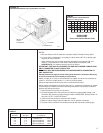
The integrated furnace control is equipped with diagnostic LED. The LED is lit continuously
when there is power to the control, with or without a call for heat. If the LED is not lit, there
is either no power to the control or there is an internal component failure within the control,
and the control should be replaced.
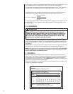
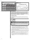
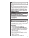
FIELD WIRE SIZE FOR 24 VOLT THERMOSTAT CIRCUITS
SOLID COPPER WIRE - AWG.
3.0 16 14 12 10 10 10
2.5 16 14 12 12 12 10
2.0 18 16 14 12 12 10
50 100 150 200 250 300
Length of Run – Feet (1)
Thermostat Load -
Amps
TABLE 6
(1) The total wire length is the distance from the furnace to the thermo-
stat and back to the furnace.
NOTE: DO NOT USE CONTROL WIRING SMALLER THAN NO. 18
AWG.