


22
7. IMPORTANT: Replace all blower doors and compartment cover after servicing the
unit. Do not operate the unit without all panels and doors securely in place.
8. Do not allow snow or other debris to accumulate in the vicinity of the appliance.
FURNACE SECTION MAINTENANCE
The unit’s furnace should operate for many years without excessive scale build-up in flue
passageways; however, it is recommended that a qualified installer, service agency, or the
gas supplier annually inspect the flue passageways, the exhaust system and the burners
for continued safe operation, paying particular attention to deterioration from corrosion or
other sources.
If during inspection the flue passageways and exhaust system are determined to require
cleaning, the following procedures should be followed (by a qualified installer, service
agency, or gas supplier):
1. Turn off the electrical power to the unit and set the thermostat to the lowest
temperature.
2. Shut off the gas supply to the unit either at the meter or at manual valve in the
supply piping.
3. Remove the furnace controls access panel and the control box cover.
4. Disconnect the gas supply piping from the gas valve.
5. Disconnect the wiring to the induced draft blower motor, gas valve, flame sensor, and
flame roll-out control, and ignitor cable. Mark all wires disconnected for proper
reconnection.
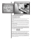
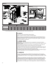
6. Remove the screws (4) connecting the burner tray to the heat exchanger mounting
panel.
7. Remove the burner tray and the manifold assembly from the unit.
8. Remove the screws (5) connecting the induced draft blower to the collector box and
screws (18) connecting the collector box to the heat exchanger center panel. Remove
the induced draft blower and the collector box from the unit.
9. Remove the screws (3) connecting the divider plate to the heat exchanger center
panel.
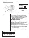
10. Remove the turbulators from inside the heat exchangers by inserting the blade of a
screwdriver under the locking tabs. Pop the tabs out of the expanded grooves of the
heat exchanger. Slide the turbulators out of the heat exchangers.
11. Direct a water hose into the outlet of the heat exchanger top. Flush the inside of each
heat exchanger tube with water. Blow out each tube with air to remove excessive
moisture.
12. Reassemble (steps 1 through 10 in reverse order). Be careful not to strip out the
screw holes used to mount the collector box and inducer blower. Replace
inducer blower gasket and collector box gasket with factory replacements if
damaged.
The manufacturer recommends that a qualified installer, service agency or the gas suppli-
er visually inspect the burner flames for the desired flame appearance at the beginning of
the heating season and approximately midway in heating season.
The manufacturer also recommends that a qualified installer, service agency or the gas
supplier clean the flame sensor with steel wool at the beginning of the heating season.
!
WARNING
LABEL ALL WIRES PRIOR TO DISCONNECTION WHEN SERVICING CONTROLS.
WIRING ERRORS CAN CAUSE IMPROPER AND DANGEROUS OPERATION
RESULTING IN FIRE, ELECTRICAL SHOCK, PROPERTY DAMAGE, PERSONAL
INJURY OR DEATH.
!
WARNING
HOLES IN THE EXHAUST TRANSITION OR HEAT EXCHANGER CAN CAUSE
TOXIC FUMES TO ENTER THE HOME. THE EXHAUST TRANSITION OR HEAT
EXCHANGER MUST BE REPLACED IF THEY HAVE HOLES OR CRACKS IN
THEM. FAILURE TO DO SO CAN CAUSE CARBON MONOXIDE POISONING
RESULTING IN PERSONAL INJURY OR DEATH.