


16
NOTICE: DERATING OF THE HEATING INPUT FOR HIGH ALTITUDE IN THE FIELD
IS UNLAWFUL IN CANADA (REFER TO CAN/CGA 2.17). UNITS INSTALLED IN
ALTITUDES GREATER THAN 2,000 FEET (610 METERS) MUST BE SHIPPED FROM
THE FACTORY OR FROM A FACTORY AUTHORIZED CONVERSION STATION
WITH THE HEATING INPUT DERATED BY 10% SO AS TO OPERATE PROPERLY IN
ALTITUDES FROM 2,000 - 4,500 FEET (610 - 1,373 METERS).
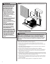
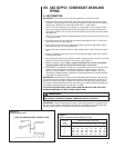
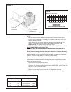
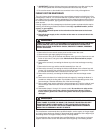
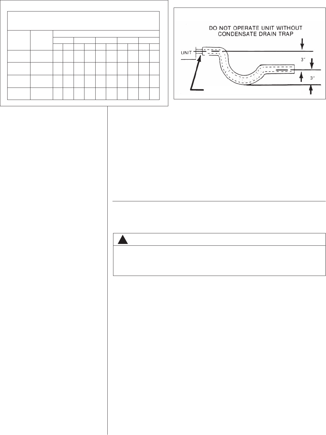
E.CONDENSATE DRAIN
The condensate drain connection of the evaporator is threaded 3/4؆ nominal P.V.C.
pipe. IMPORTANT: Install a condensate trap to ensure proper condensate drainage.
See Figure 16.
IX. WIRING
A. POWER SUPPLY
1. All wiring should be made in accordance with the National Electrical Code.
Consult the local power company to determine the availability of sufficient power to
operate the unit. Check the voltage at power supply to make sure it corresponds to
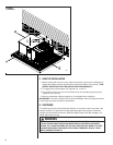
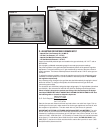
the unit’s RATED VOLTAGE REQUIREMENT. Install a branch circuit disconnect
near the rooftop, in accordance with the N.E.C., C.E.C. or local codes. A bracket is
provided with the unit for mounting of the disconnect. See Figure 17.
2. It is important that proper electrical power is available at the unit. Voltage should not
vary more than 10% from that stamped on the unit nameplate. On three phase units,
phases must be balanced within 3%.
3. For branch circuit wiring (main power supply to unit disconnect), the minimum wire size
for the length of run can be determined from Table 3 using the circuit ampacity found on
the unit rating plate. Use the smallest wire size allowable in Table 4 from the unit dis-
connect to unit.
NOTE: A bracket is provided with the unit for mounting the branch circuit disconnect to
the unit. This is the recommended location for the disconnect. See Figure 17.
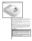
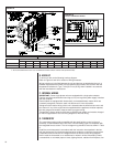
4. For through the base wiring entry reference Figure 18. All fittings and conduit are field
supplied for this application. Reference the chart with Figure 18 for proper hole and
conduit size.
ONE 1 21 1 30 1 34 1 39 3 45
40,000
TEN 13 30 15 0 15 36 16 30 37 30
ONE 0 54 101 316230
60,000
TEN 9010 0 10 24 11 0 25 0
ONE 0 41 0 45 0 47 0 50 1 53
80,000
TEN 6 45 7 30 7 48 8 15 18 45
ONE 0 33 0 36 0 38 0 40 1 30
100,000
TEN 5 24 60615 6 36 15 0
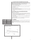
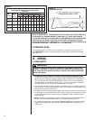
METER TIME IN MINUTES AND SECONDS FOR NORMAL
INPUT RATING OF FURNACES EQUIPPED FOR NATURAL
OR LP GAS
INPUT
BTU/HR
METER
SIZE
CU. FT.
HEATING VALUE OF GAS BTU PER CU. FT.
900 1000 1040 1100 2500
MIN. SEC. MIN. SEC. MIN. SEC. MIN. SEC. MIN. SEC.
TABLE 3
FIGURE 16
CONDENSATE DRAIN
DO NOT OVERTIGHTEN DRAIN FITTING
!
WARNING
TURN OFF THE MAIN ELECTRICAL POWER AT THE BRANCH CIRCUIT DIS-
CONNECT CLOSEST TO THE UNIT BEFORE ATTEMPTING ANY WIRING. FAIL-
URE TO DO SO CAN CAUSE ELECTRICAL SHOCK RESULTING IN PERSONAL
INJURY OR DEATH.