


18
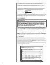
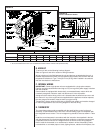
B. HOOK-UP
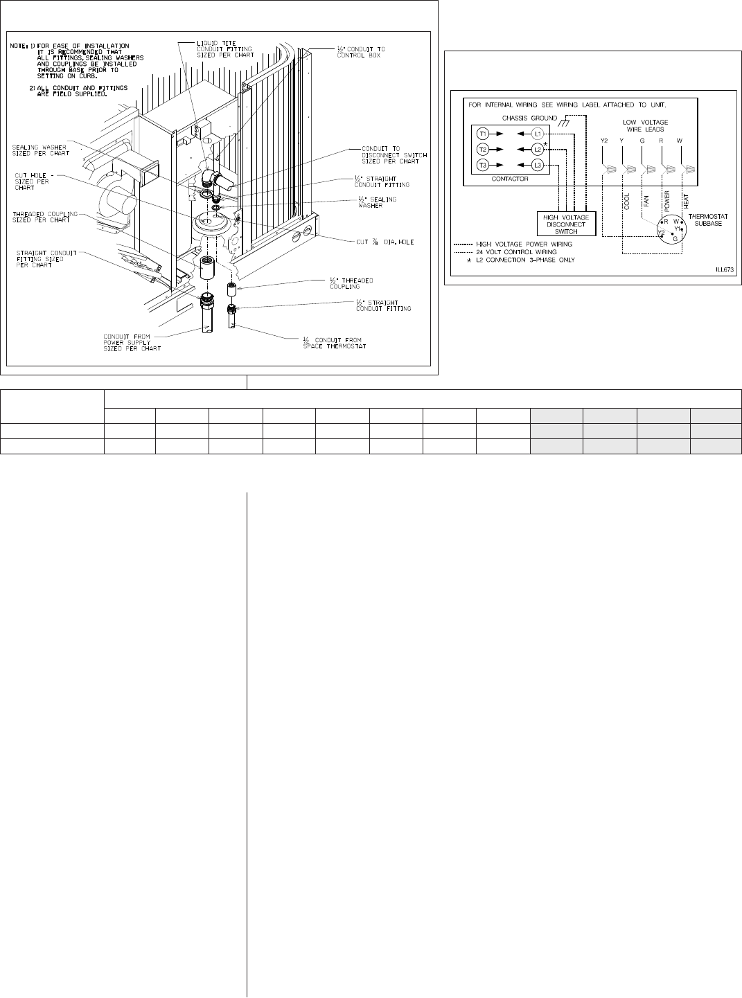
To wire unit, refer to the following hook-up diagram.
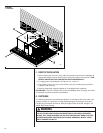
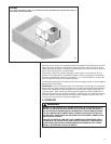
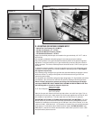
Refer to Figures 3 and 18 for location of wiring entrances.
Wiring to be done in the field between the unit and devices not attached to the unit, or
between separate devices which are field installed and located, shall conform with the
temperature limitation for Type T wire [63°F rise (35°C)] when installed in accordance
with the manufacturer’s instructions.
C. INTERNAL WIRING
IMPORTANT: Some single phase units are equipped with a single pole contactor.
Caution must be exercised when servicing as only one leg of the power supply is broken
with the contactor.
Some models are equipped with electronically commutated blower motors which are
constantly energized, unless the main unit disconnect is in the off position.
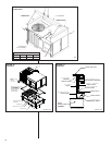
A diagram of the internal wiring of this unit is located under the electrical box cover and
this manual. If any of the original wire as supplied with the appliance must be replaced,
the wire gauge and insulation must be same as original wiring.
Transformer is factory wired for 230 volts on 208/230 volt models and must be changed
for 208 volt applications. See unit wiring diagram for 208 volt wiring.
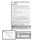
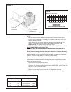
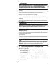
D. THERMOSTAT
The room thermostat must be compatible with the spark ignition control on the unit.
Generally, all thermostats that are not of the “current robbing” type are compatible with
the integrated furnace control. The low voltage wiring should be sized as shown in Table
6.
Install the room thermostat in accordance with the instruction sheet packed in the box
with the thermostat. Run the thermostat lead wires inside the compressor access panel
compartment and connect to low voltage terminals as shown on the wiring diagram.
Never install the thermostat on an outside wall or where it will be influenced by drafts,
concealed hot or cold water pipes or ducts, lighting fixtures, radiation from fireplace, sun
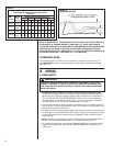
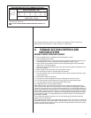
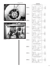
WIRE SIZE, AWG
FIGURE 18
FIGURE 19
TYPICAL THERMOSTAT WIRING
14
1/2؆
7/8؆
12
1/2؆
7/8؆
10
1/2؆
7/8؆
8
3/4؆
1-31/32؆
6
1؆
1-23/64؆
4
1؆
1-23/64؆
3
1-1/4؆
1-23/32؆
2
1-1/4؆
1-23/32؆
1
1-1/2؆
1-31/32؆
0
1-1/2؆
1-31/32؆
00
2؆
2-15/32؆
000
2؆
2-15/32؆
CONDUIT SIZE
HOLE SIZE
I658
NOTES: 1. DETERMINE REQUIRED WIRE SIZE FROM MINIMUM CIRCUIT AMPACITY SHOWN IN INSTALLATION & OPERATING INSTRUCTION.
2. BOTTOM POWER ENTRY WILL NOT ACCOMMODATE WIRE LARGER THAN #2 AWG (SHADED AREA).