


9
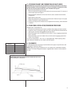
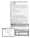
Recommended
Clearance
Location
48؆ A - Front
18؆ B - Condenser Coil
12؆* C - Duct Side
36؆ D - Evaporator End
60؆ E - Above
*Without Economizer. 57 With Economizer
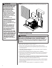
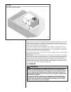
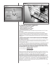
C. ATTACHING EXHAUST AND COMBUSTION AIR INLET HOODS
IMPORTANT: Do not operate this unit without the exhaust/combustion air inlet hood
properly installed. This hood is shipped in a carton in the blower compartment inside
the unit and must be attached when the unit is installed. See Figure 3.
To attach exhaust/combustion air inlet hood:
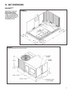
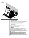
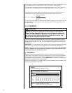
1. Remove screws securing blower access panel and remove access panel. For location of
blower access panel, see Figure 2.
2. Remove exhaust/combustion air inlet hood from the carton, located inside the blower
compartment.
3. Attach blower access panel.
4. Attach the combustion air inlet/exhaust hood with screws. Reference Figure 3 for proper
location. Screws are in carton with the hood.
5. Vent the unit using the flue exhaust hood, as supplied from the factory, without alteration
or addition.
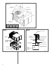
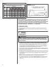
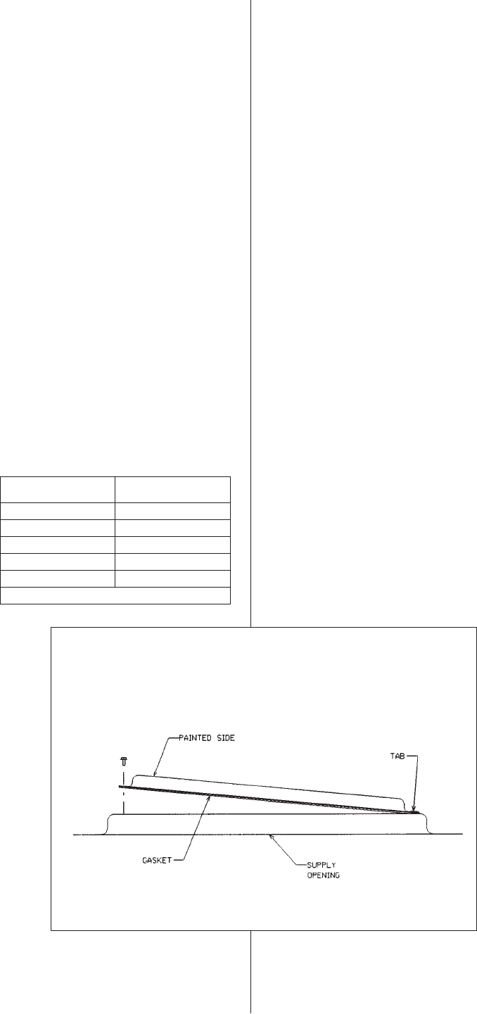
D. COVER PANEL INSTALLATION/CONVERSION PROCEDURE
DOWNFLOW TO HORIZONTAL
1. Remove the screws and covers from the outside of the supply and return sections.
2. Install the covers in the bottom supply and return openings with the painted side up.
See Figure 6. Use the existing gasket to seal the covers.
3. Secure the supply cover to the base of the unit with 1 screw, engaging prepunched
tab in unit base.
4. Secure the return cover to the base of the unit with screws engaging prepunched
holes in the unit base.
This unit is provided with 2 - 25؆ X 16؆ X 1؆ disposable filters. When replacing filters,
ensure they are inserted fully to the back to prevent bypass.
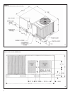
E. CLEARANCES
The following minimum clearances must be observed for proper unit performance and
serviceability. Reference Figure 7.
NOTE: Supply duct may be installed with “0’ inch clearance to combustible materials,
provided 1؆ minimum Fiberglass insulation is applied either inside or on the outside of
the duct.
FIGURE 6
COVER GASKET DETAIL FOR UNITS SHIPPED FOR DOWNFLOW APPLICATION
BEING CONVERTED TO HORIZONTAL
I631