


15
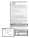
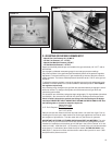
D. ADJUSTING OR CHECKING FURNACE INPUT
– Natural Gas Line Pressure 5
؆؆
- 10.5
؆؆
W.C.
– LP Gas Line Pressure 11
؆؆
- 1
3
؆؆
W.C.
– Natural Gas Manifold Pressure 3.5
؆؆
W.C
– L
P Gas Manifold Pressure - 10
؆؆
W.C
.
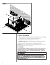
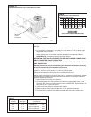
Supply and manifold pressure taps are located on the gas valve body 1/8؆ N.P.T. and on
the manifold.
Use a properly calibrated manometer gauge for accurate gas pressure readings.
Only small variations in the gas flow should be made by means of the pressure regulator
adjustment. Furnaces functioning on LP gas must be set by means of the tank or branch
supply regulators. The furnace manifold pressure should be set at 10؆ W.C. at the gas con-
trol valve.
To adjust the pressure regulator, remove the regulator cap and turn the adjustment screw
clockwise to increase pressure or counterclockwise to decrease pressure. Then replace
the regulator cap securely.
Any necessary major changes in the gas flow rate should be made by changing the size of
the burner orifices. To change orifice spuds, shut off the manual main gas valve and
remove the gas manifold.
For elevations up to 2,000 feet, rating plate input ratings apply. For high altitudes (elevations
over 2,000 ft.), see conversion kit index 92-21519-XX for derating and orifice spud sizes.
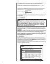
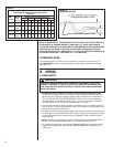
Check of input is important to prevent over-firing of the furnace beyond its design-
rated input. NEVER SET INPUT ABOVE THAT SHOWN ON THE RATING PLATE. Use
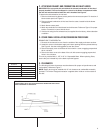
the following table or formula to determine input rate.
Heating Value of Gas
(BTU/Cu. Ft.) x 3600
Cu. Ft. Per Hr. Required =
Time in Seconds
(for 1 Cu. Ft.) of Gas
Start the furnace and measure the time required to burn one cubic foot of gas. Prior to
checking the furnace input, make certain that all other gas appliances are shut off, with
the exception of pilot burners. Time the meter with only the furnace in operation.
IMPORTANT NOTE FOR ALTITUDES ABOVE 2,000 FEET (610 METERS): The main
burner orifices in your furnace and in these kits are sized for the nameplate input and
intended for installations at elevations up to 2,000 feet in the USA or Canada, or for ele-
vations of 2,000 - 4,500 feet (610 -1,373 meters) in Canada if the unit has been derated
at the factory. For elevations above 2,000 feet (610 meters) IN THE USA ONLY (see
ANSI-Z223.1), the burner orifices must be sized to reduce the input 4% for each 1,000
feet (305 meters) above sea level.
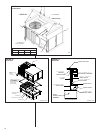
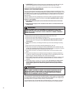
FIGURE 14
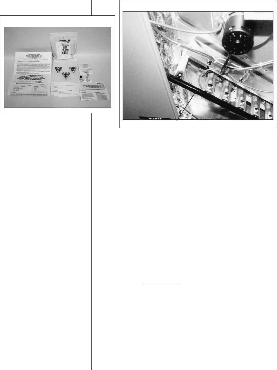
FIGURE 15
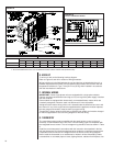
MANIFOLD PIPE