


PRO
3
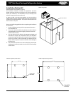
Side Mount Packaged Refrigeration System Installation and Operations Manual, May 2008 13
PRO
3
Side Mount Packaged Refrigeration System
N.C.
Line
8(3)A250V~
1 2 3 4 5 66
9 10 11 12
5(1)A
Max
20A
Comp
Def
Evap.
Room
7
Hot Key/IV probe
TTL or. X-REP output
Fan
8
20(8)A250V~
N.C.
Line
8(3)A250V~
1 2 3 4 5 6 6
9 10 11 12
8(3)A
Max
16A
Comp
Def Fan
Evap.
Room
7
Hot Key/IV probe/
TTL or X-REP output
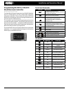
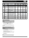
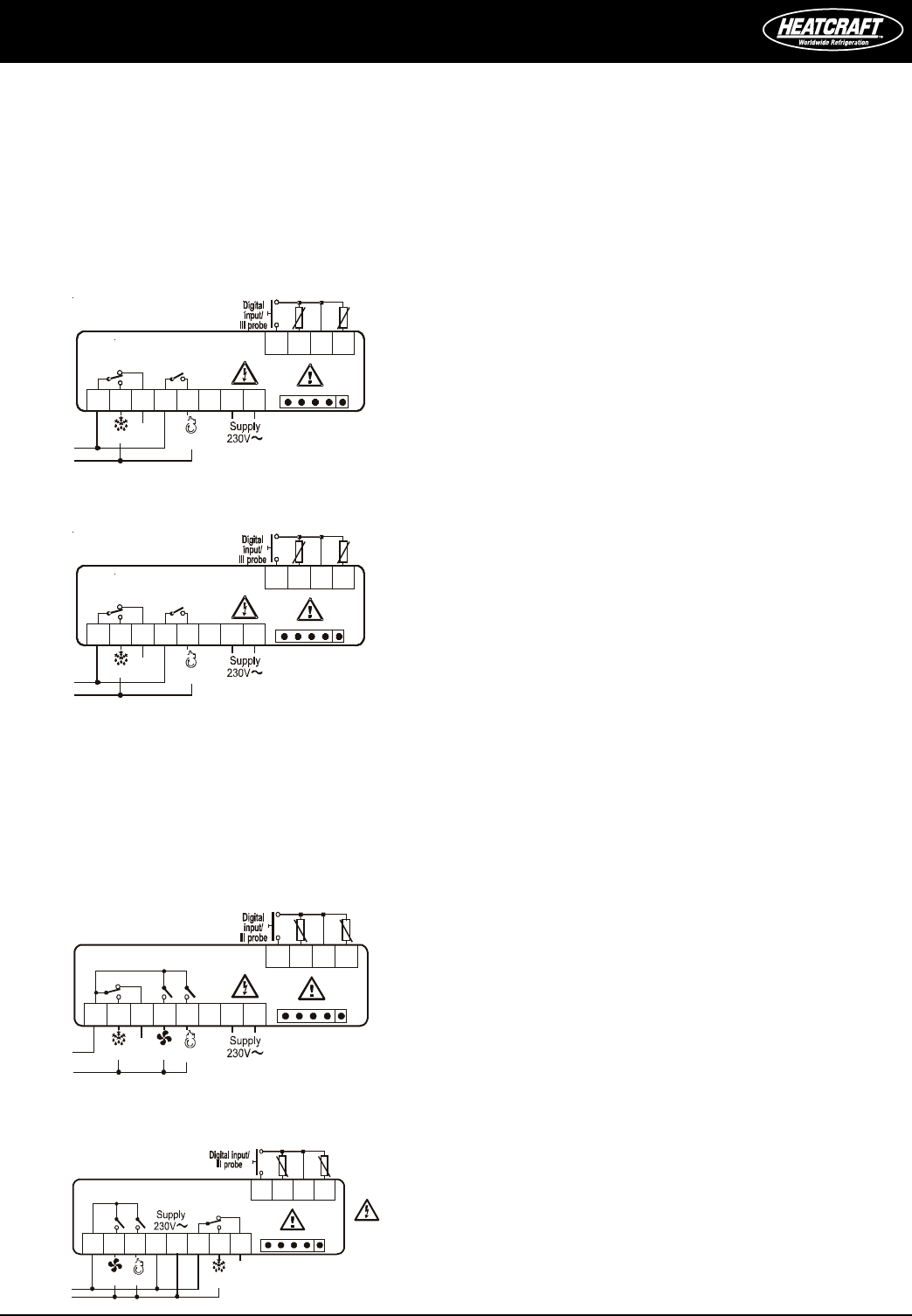
NOTE: The compressor relay is 8(3)A or 16(6)A according to the model.
20A comp. relay - 230 VAC
Service Information
All PRO
3
packaged refrigeration system units are designed for
maximum durability, reliability and simplicity. The PRO
3
packaged
refrigeration system comes to you ready for operation, fully charged
and with all controls preset at the factory. The following information
is provided as an aid in the event that service is required.
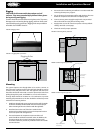
Maintenance
The evaporator section of a PRO
3
packaged refrigeration system
should be checked at least once for proper defrosting because the
amount and pattern of frosting can vary greatly.
The frost build-up is dependent on the temperature of the room,
the type of product being stored, how often new product is brought
into the room and percentage of time the door to the room is open.
It may be necessary to periodically change the number of defrost
cycles or adjust the duration of defrost.
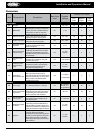
System Standard Maintenance Guidelines
After rst year of operation and under normal usage, maintenance
should cover the following items at least once every six months:
1. Check and tighten ALL electrical connections.
2. Check all wiring and insulators.
3. Check contactors for proper operation and for worn contact
points.
4. Check all fan motors. Tighten motor mount bolts/ nuts and
tighten fan set screws.
5. Clean the condenser coil surface.
6. Check the operation of the control system. Make certain all
safety controls are operating properly.
7. Check all defrost controls for proper function.
8. Clean the evaporator coil surface.
9. Clean the drain pan and check the drain pan and drain line for
proper drainage.
CAUTION: Unit is critically charged, care must be taken
not to reduce the system refrigerant charge while
taking pressure readings. Technician must compensate
for any refrigerant that might escape the unit into the
gauge tubing.
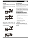
Connections
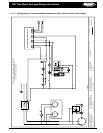
XR40CX
The X-REP output excludes the TTL output. It’s present in the
following codes: XR40CX- xx2xx, XR40CX –xx3xx; XR40CX –xx6xx;
XR40CX –xx7xx;
The digital input configurable as third probe is present in the
following codes: XR40CX- xx4xx, XR40CX –xx5xx; XR40CX –xx6xx;
XR40CX –xx7xx;
8A compressor
N.C.
1 2 3 4 5 6 7
9 10 11 12
Comp
Def
E
v
a
p
.
R
o
o
m
8
Hot Key/IV Probe
TTL or X-REPoutput
8(3)A250V 8(3)A250V
Line
20A compressor
N.C.
1 2 3 4 5 6 7
9 10 11 12
Comp
Def
E
v
a
p
.
R
o
o
m
8
Hot Key/IV probe
TTL or X-REP output
8(3)A250V 20(8)A250V
Line
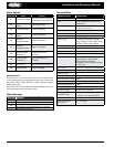
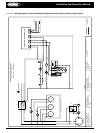
XR60CX
The X-REP output excludes the TTL output. It’s present in the
following codes: XR60CX- xx2xx, XR60CX –xx3xx; XR60CX –xx6xx;
XR60CX –xx7xx;
The digital input configurable as third probe is present in the
following codes: XR60CX- xx4xx, XR60CX –xx5xx; XR60CX –xx6xx;
XR60CX –xx7xx;
8A or 16A comp. relay - 230 VAC