


2
Installation and Operations Manual
© 2008 Heatcraft Refrigeration Products LLC
Table of Contents
Inspection............................................................................3
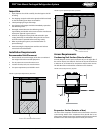
Installation Requirements .................................................3
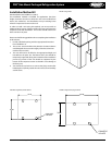
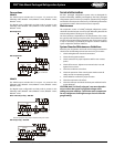
Recommended Unit Placement
FIGURE 1: System Space Requirements | Back View
FIGURE 2: System Space Requirements | Side View
Access Requirements .........................................................3
Condensing Unit Section (Exterior of box)
FIGURE 3: Access Requirements | Top View
Evaporator Section (Interior of box)
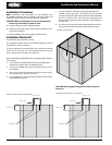
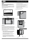
Installation Procedures .................................................. 4-7
FIGURE 4: Cutout Location
FIGURE 5: Cutout Dimensions | Small Cabinet
FIGURE 6: Cutout Dimensions | Large Cabinet
FIGURE7: Plug Detail
FIGURE 8: Plug Detail | Small Cabinet
FIGURE9: Plug Detail | Large Cabinet
Rigging
FIGURE10: Rigging Holes
FIGURE 11: Rigging Holes | Front View
Mounting
FIGURE12: Mounting Holes | Side View
FIGURE 13: Mounting Holes | Front View
FIGURE 14: Mounting Holes | Top View
Electrical Connection
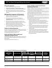
Refrigeration Sequence of Operation ...............................7
TABLE 1 Model PST | Default Temperature Control Settings
Cooler Temperature Control
Coolers: Air-defrost Operation
Cooler with Electric Defrost and Freezer Temperature/
Defrost Control
Cooler with Electric Defrost and Freezer Sequence of
Operation
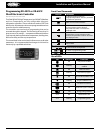
Programming Electronic Controller ............................8-16
Dixell Electronic Controller (XR40CX and XR60CX)
Front Panel Commands ..................................................................8
Use of LEDs...........................................................................................8
Max. & Min. Temperature Memorization: .................................9
How to See the Min. Temperature
How to See the Max. Temperature
How to Reset the Max. & Min. Temperature Recorded
Main Functions: .................................................................................9
How to see the set-point
How to change the set-point
How to start a manual defrost
How to change a parameter value
The Hidden Menu .............................................................................9
How to Enter the Hidden Parameters
How to Move a Parameter from the Hidden Menu
How to Lock the Keyboard
The Continuous Cycle
The On/O Function
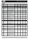
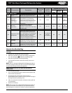
Parameters .................................................................................10-11
Regulation
Display
Defrost
Fans (XR60CX ONLY)
Alarms
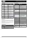
How to use the Hot Key ................................................................11
How to program a Hot Key from the Instrument
Alarm Signals ...................................................................................12
Alarm Recovery
Other Messages ..............................................................................12
Technical Data .................................................................................12
Connections .....................................................................................13
Service Information..........................................................13
Maintenance
System Standard Maintenance Guidelines
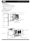
Drain Pan Removal..............................................................................14
FIGURE 15: Drain Pan Removal | View A
FIGURE 16: Drain Pan Removal | View B
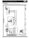
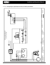
Wiring Diagrams .........................................................15-18
DIAGRAM 1 High Temperature Cooler | Air Defrost | Large Cabinet
DIAGRAM 2
High Temperature Cooler | Air Defrost | Small Cabinet
DIAGRAM 3 Freezer and Medium Temperature Cooler | Electric Defrost | Small Cabinet
DIAGRAM
4 Freezer and Medium Temperature Cooler | Electric Defrost | Large Cabinet
Performance, Capacities and Specications ..................19
TABLE 2 Cooler Application | Air Defrost | BTUH at 95°F ambient
TABLE
3 Cooler Application | Electric Defrost | BTUH at 95°F ambient
TABLE
4 Freezer Application | Electric Defrost | BTUH at 95°F ambient
TABLE
5 Specications
Dimensions ................................................................. 20-21
DIAGRAM 5 Dimensions | Small Cabinet: 1-fan | Top view
DIAGRAM
6 Dimensions | Small Cabinet: 1-fan | Side view
DIAGRAM
7 Dimensions | Small Cabinet: 1-fan | Back view
DIAGRAM
8 Dimensions | Large Cabinet: 2-fan | Top view
DIAGRAM
9 Dimensions | Large Cabinet: 1-fan | Side view
DIAGRAM
10 Dimensions | Large Cabinet: 1-fan | Back view
Replacement Parts by InterLink .....................................22
TABLE 6 Replacement Parts List
Warranty Statement ........................................................23