


6
Installation and Operations Manual
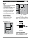
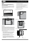
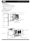
Rigging
CAUTION: Avoid contact with sharp edges and coil
surfaces. They are a potential injury hazard. Wear gloves
during moving and rigging.
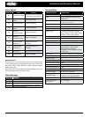
Caution should be exercised when moving these units. To prevent
damage to the unit housing during rigging, cables or chains used
must be held apart by spacer bars. Rigging holes are provided on
all models. See FIGURES 10 and 11.
FIGURE 10: Rigging Holes
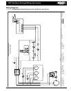
FIGURE 11: Rigging Holes | Front View
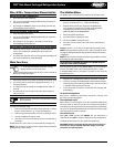
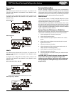
Mounting
The system requires two through-bolts to be used to connect to
the roof panel. A minimum of four through-bolts should be used to
connect to the side panel of the box. The opposite side of the box
should be reinforced with wood or metal to prevent the bolts from
pulling through the panel. See FIGURES 12, 13 and 14 for locations.
Through bolts should be insulated or non-conductive to prevent
sweating. All penetrations to the box should be caulked to prevent
moisture from entering the box.
1. Install two through bolts to secure the unit to the wall. The inside
of the box should be reinforced with wood or metal for proper
when mounting of the unit to the box with through bolts.
2. Install and secure the roof of the box. Inside the box,
provisions have been made to secure the evaporator section
to the roof panel with through bolts.
3. The area between the evaporator section and the roof
panel should be caulked to meet NSF codes. In addition, the
openings where the unit was lowered into the box panel
should be caulked to prevent any inltration from the outside
area into the box.
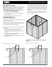
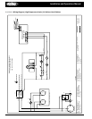
Mounting
holes
Front panels
removed
for clarity
Mounting holes
Mounting holes
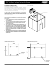
Top not shown
for clarity
Mounting holes
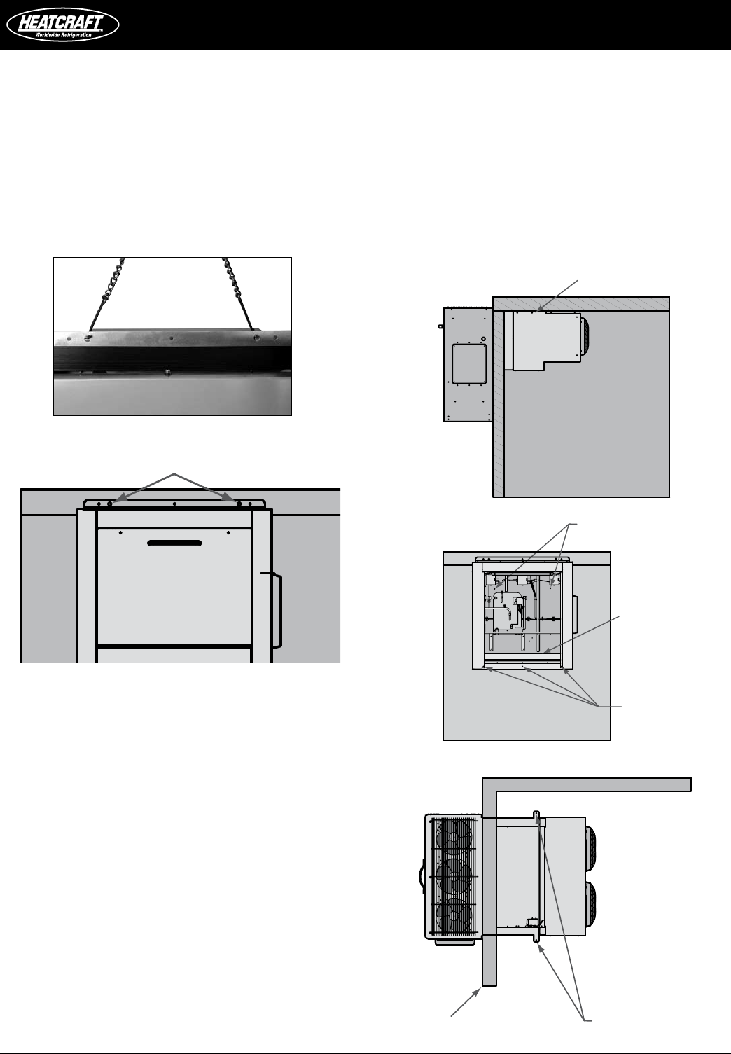
4. Ensure that the condensing unit airow is not obstructed after
removing the temporary support.
5. Do not obstruct the evaporator airow with shelving. The area
below the evaporator should be left completely open.
6. Connect unit to power supply through knock-out provided
above electrical box using all local wiring codes.
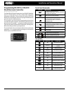
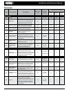
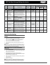
7. Apply power to unit. All controls are preset to factory default
settings. See Table 1 (next page).
8. Check the unit for proper operation.
Rigging holes
FIGURE 12: Mounting Holes | Side View
FIGURE 13: Mounting Holes | Front View
FIGURE 14: Mounting Holes | Top View